
Ed Bradley’s Web: Weaving Networks, Security, Cloud, and Code.
Introduction
With the high-level vision of my home lab complete, the next step is to build the network foundation. Everything else in this environment — servers, virtualization, security, monitoring — relies on a reliable and well-structured network.
To avoid the chaos of spreadsheets and sticky notes, I’m using NetBox (Cloud) as my source of truth. I'm using NetBox to track:
- IPAM (IP Address Management): subnets and host assignments per VLAN
- VLANs: IDs, names, and roles across the lab
- Device inventory: switches, firewalls, routers, and their host and management IPs
- Connections: uplinks, trunks, and physical interface mappings
Every element you’ll see in the diagram below will be added along the way to NetBox as structured data. This ensures my documentation and implementation stay aligned — exactly how enterprises run their networks.
High-Level Topology
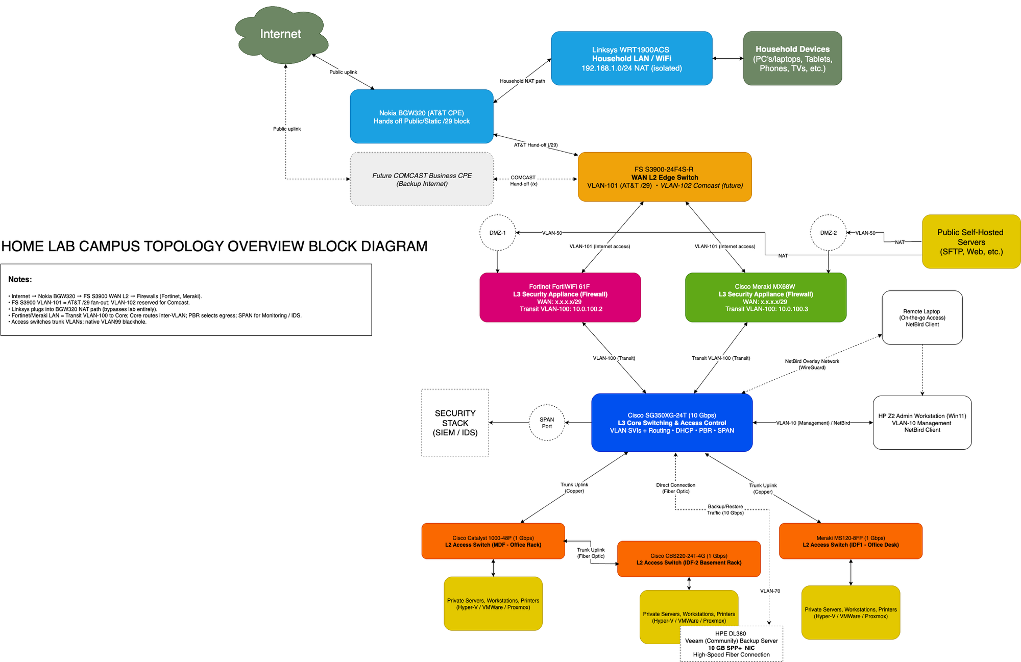
Above is the campus-style topology of my lab network. At the center is the Cisco SG350XG-24T, which acts as the Layer 3 core switch and VLAN router. Branching out from it are:
- FS S3900-24F4S-R (Edge Switch): connects the AT&T BGW320 CPE and uplinks both firewalls.
- FortiWiFi 61F and Meraki MX68W: side-by-side firewalls, each with a dedicated VLAN trunk to the core.
- Cisco Catalyst 1000-48P-4G-L & Meraki MS120-8FP: PoE access switches for servers, Wi-Fi, and lab devices.
- Cisco CBS220-24T-4G: basement access switch, home to my louder servers and the backup node.
- Linksys WRT1900ACS: separate household Wi-Fi router, plugged directly into the AT&T CPE and isolated from the lab.
Each of these devices is represented in NetBox with interfaces and connections mapped, making the diagram more than just a drawing — it’s a reflection of the structured inventory.
Why VLAN Segmentation Matters
Instead of one big flat network, VLANs allow me to separate traffic logically: management, servers, IoT, Wi-Fi, and DMZ all live in different segments. This design:
- Increases security (e.g. "IoT can’t talk to servers").
- Improves performance (smaller broadcast domains).
- Adds clarity (traffic roles are clearly defined and tracked in NetBox).
- Mirrors real-world best practices — this is exactly how enterprise environments enforce policy boundaries.
By using NetBox to define VLANs up front, I can avoid misconfigurations. Each VLAN ID, subnet, and description exists in NetBox first, and then I configure the switches and firewalls to match.
Next Steps
In the next part of this post, I’ll document the VLAN implementation itself:
- Creating VLANs (on the core and edge switches).
- Propagating VLANs across the access switches.
- Assigning interfaces and configuring uplinks.
This will turn the diagram and design into a working, segmented network.
VLAN Definitions
While sketching out the network topology, I began by mapping the VLAN design in a simple Excel spreadsheet, shown below. This helped me visualize how different segments of the lab would be organized before diving into actual configuration.
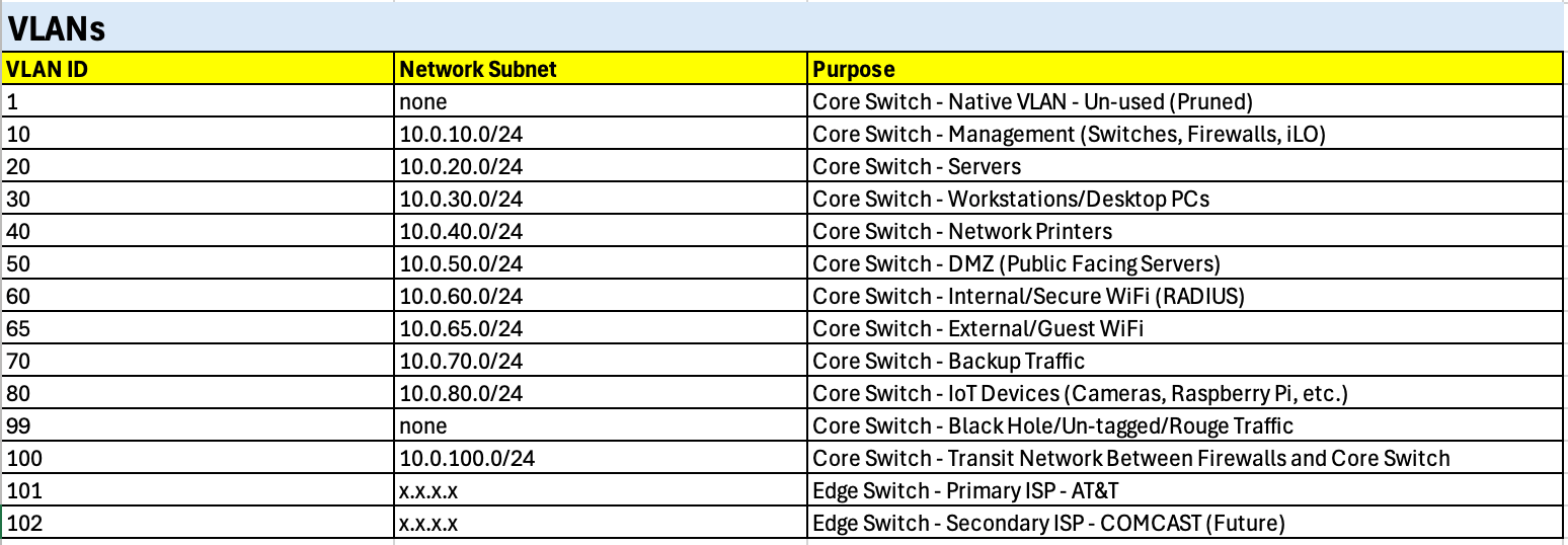
The core switch serves as the primary point of VLAN definition, hosting the majority of functional segments such as Servers, Workstations, Printers, and Management. Additional VLANs are defined on the edge switch, specifically to separate upstream ISP traffic (AT&T and Comcast).
Each VLAN is assigned a clear purpose based on function, ensuring that traffic types remain logically isolated while still being easy to manage and extend throughout the lab.
Security Note: Native VLAN Handling
By default, most switches use VLAN 1 as the native VLAN for untagged traffic. However, VLAN 1 is widely known and often exploited in attacks (e.g., VLAN hopping). As a security measure, I’ve chosen to disable VLAN 1 across all switches and instead configure VLAN 99 as a “black hole” VLAN.
This means:
- Any untagged or rogue traffic that lands on a trunk or misconfigured port gets dumped into VLAN 99.
- VLAN 99 has no active hosts or gateway, so the traffic is effectively isolated and dropped.
- This reduces the risk of accidental misconfigurations or malicious attempts to inject untagged packets into production VLANs.
Using a dedicated “parking lot” VLAN like this is a common best practice in enterprise networks, and it’s one I’m applying in the lab to improve segmentation security and mirror real-world design standards.
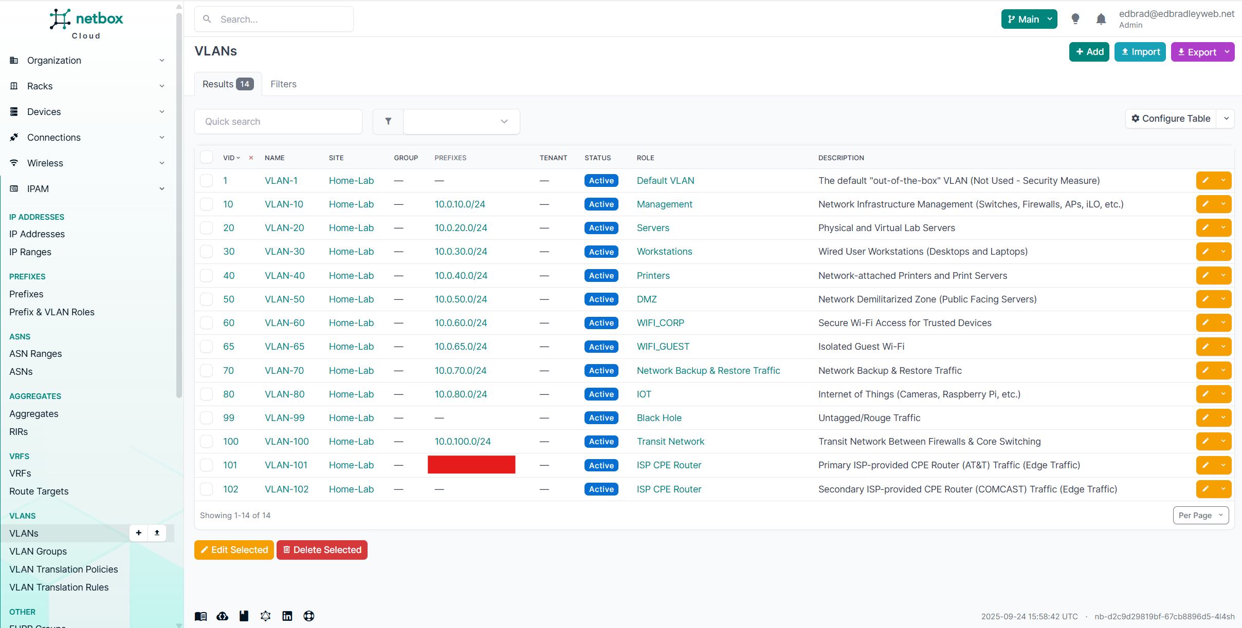
Next, I documented the VLANs in NetBox, transforming the initial Excel draft into a structured source of truth. NetBox’s built-in IP Address Management (IPAM) capabilities make it ideal for this step, providing centralized tracking of IP address allocations, VLAN assignments, and relationships across the network.
I entered each VLAN from the spreadsheet into the NetBox database, where they are now linked not only to their unique VLAN IDs but also to their associated prefixes and functional roles. This ensures that every VLAN is consistently defined, properly connected to its subnet, and clearly aligned with its intended purpose in the lab:
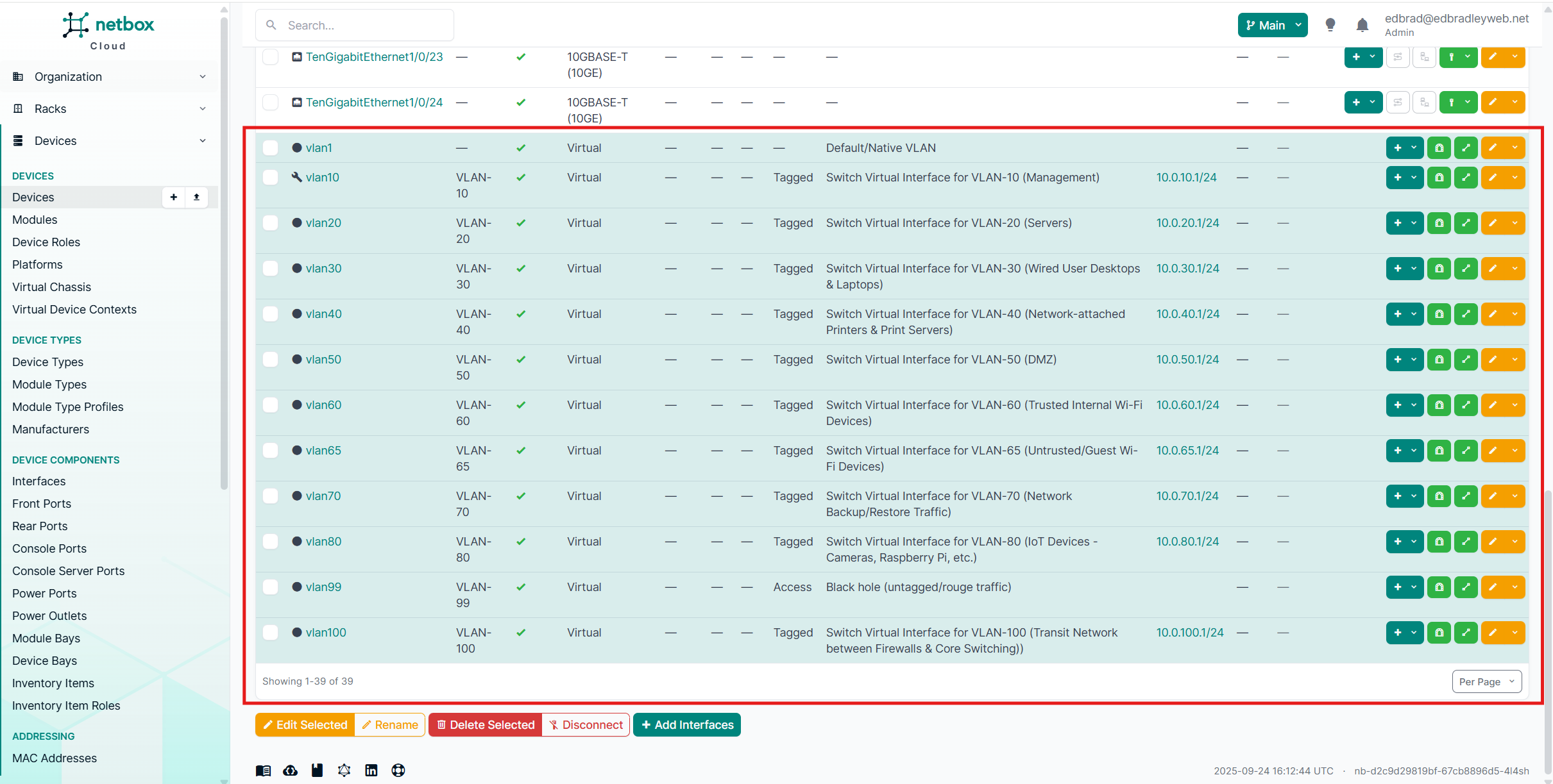
The VLANs were then associated with the switch hardware definitions inside the NetBox database. Using NetBox’s DCIM (Data Center Infrastructure Management) features, I was able to document these virtual interfaces in detail — including their VLAN assignments, descriptions, and the IP addresses allocated to each.
Capturing this information in NetBox isn’t just about neat documentation — it’s about creating a single, authoritative source of truth for the network. By tying VLANs directly to the switch hardware:
- Accuracy is improved – Every interface, VLAN, and IP address is explicitly tracked against the hardware it belongs to.
- Consistency is enforced – The same VLAN IDs and prefixes are used across devices, preventing drift or accidental mismatches.
- Troubleshooting is easier – If there’s ever a configuration issue, I can quickly check NetBox to confirm which VLANs and IPs should exist on a given port before digging into CLI configs.
- Professional discipline – This mirrors how enterprise environments manage infrastructure, ensuring the logical and physical layers are always in sync.
In other words, NetBox isn’t just a documentation tool here — it’s actively shaping how I build and maintain the lab, helping me work the same way a production network team would.
Core Switch:
Edge Switch:
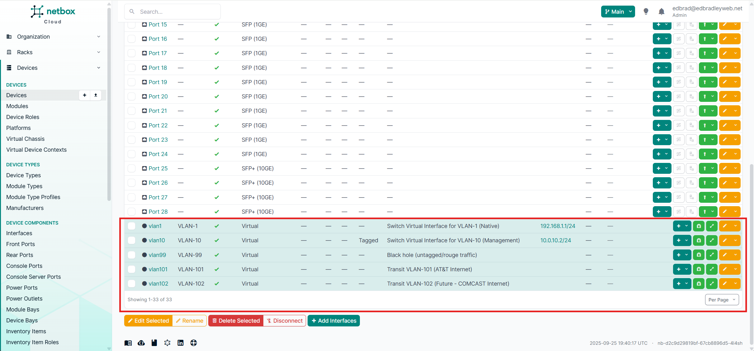
VLANs 10 and 99 are extended to the edge switch to provide consistent management access and enforce the neutralization of VLAN 1 by redirecting untagged or rogue traffic into the designated black hole VLAN (99).
Meanwhile, VLANs 101 and 102 are reserved exclusively for separating AT&T and the future Comcast internet connections. These VLANs do not require their own IP addresses, since no devices reside directly within them. Instead, they serve purely as transit VLANs, carrying traffic between the ISP CPE equipment and the two firewalls. In effect, they act as dedicated conduits, fanning provider traffic across both the FortiWiFi and Meraki appliances without exposing internal hosts to these segments.
📌 Transit VLANs Explained
Not every VLAN in a network is used to host servers, workstations, or IoT devices. Some VLANs exist purely as transit networks — dedicated paths for moving traffic between devices.
In this lab, I’ve created VLANs specifically to carry traffic from the AT&T and (eventually) Comcast ISPs into my firewalls.
- No internal IPs required: Because these VLANs don’t host any devices, there’s no need to define subnets for them. The only IP addresses involved are those on the firewalls’ WAN interfaces, which connect directly to the public internet.
- Purpose-built isolation: By keeping ISP traffic in its own VLAN, I ensure it never mixes with internal LAN traffic. Each firewall gets a clean, isolated handoff from the Edge Switch.
- Security benefit: This design makes the boundary between WAN and LAN traffic explicit, limiting opportunities for configuration mistakes and keeping untrusted ISP traffic separate from the rest of the lab.
In short, these VLANs act as simple conduits, “fanning” traffic from the ISPs across to the firewalls, without ever routing it through the core switch or mixing it with internal segments.
Now I'm ready to configure the switching infrastructure using my NetBox source of truth as my guide.
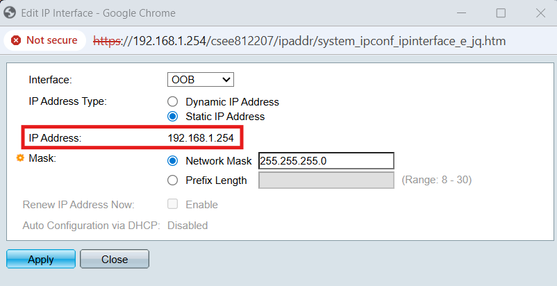
Core Switch (Cisco SG350XG-24T) Configuration
In addition to the traditional CLI, the Cisco core switch also provides a convenient web-based GUI for configuration. A dedicated out-of-band (OOB) management port can be used to access this interface. I connected my laptop’s NIC (configured with a compatible IP address of 192.168.1.2) and established a HTTPS session to the switch’s default management address (192.168.1.254):
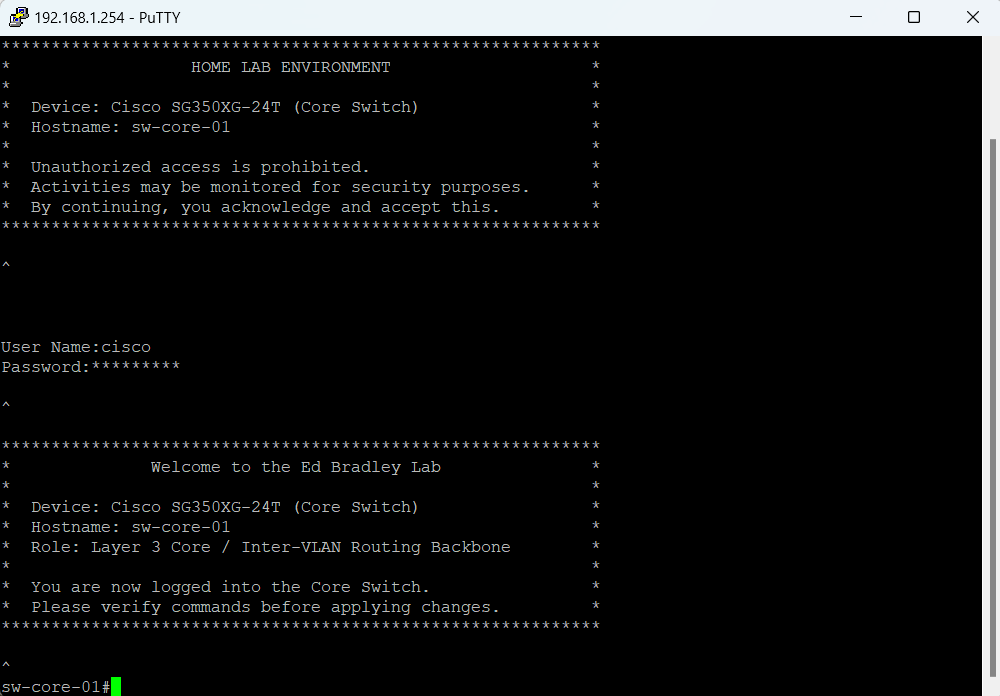
After logging in and replacing the default password (a required first step), I updated the hostname to match the entry in NetBox. I also applied the previously prepared login and welcome banners so that both the web console and CLI now present consistent identification details:
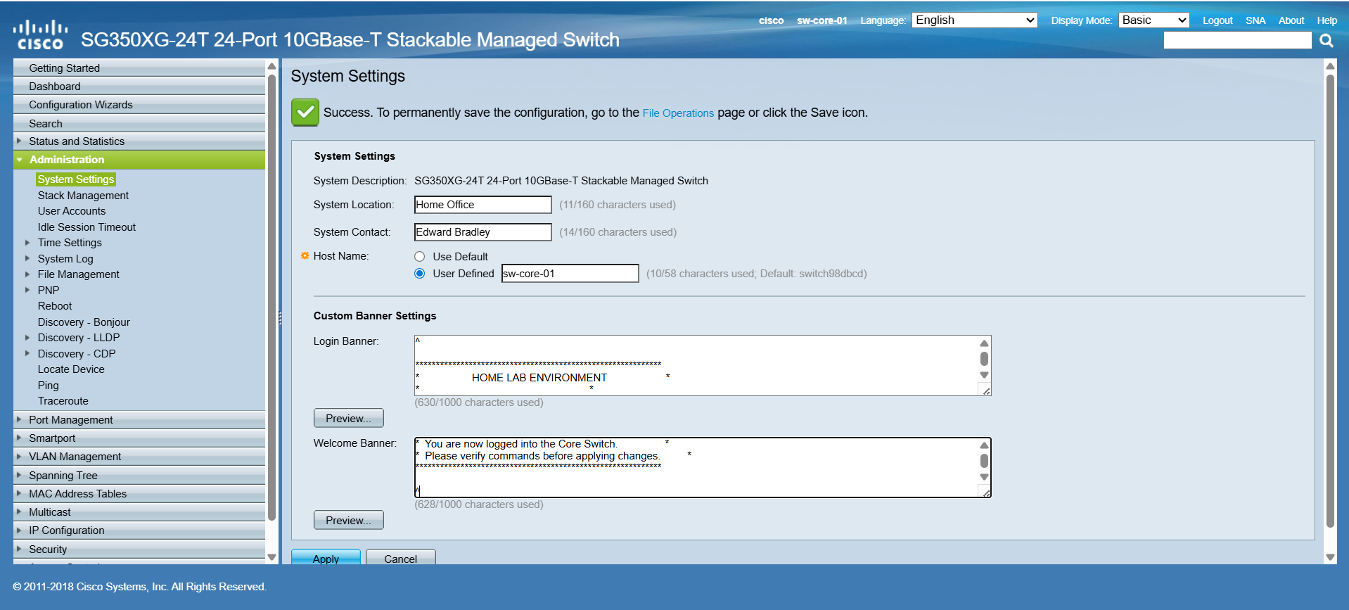
This is reflected in the CLI:
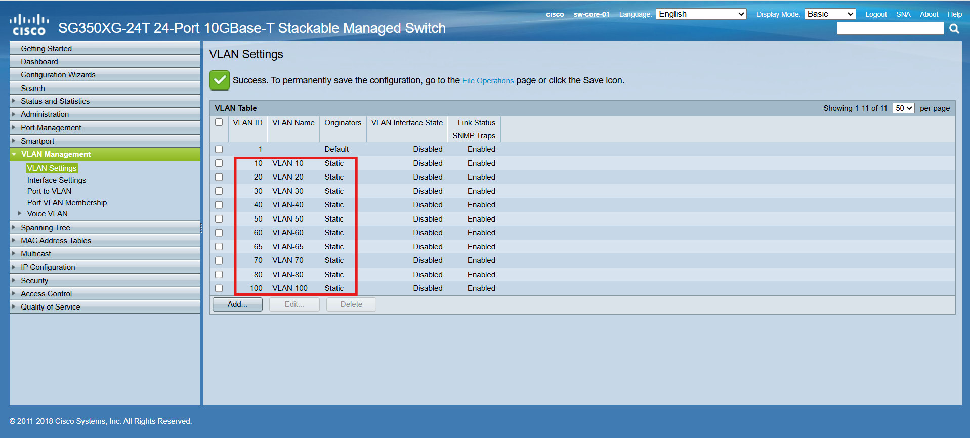
I first used the Web GUI to define the new VLANs under VLAN Management → VLAN Settings:
Next, I created the initial DHCP pools for each VLAN. Each pool is configured to lease up to 76 addresses, covering the range from .25 through .100 within its respective /24 subnet:
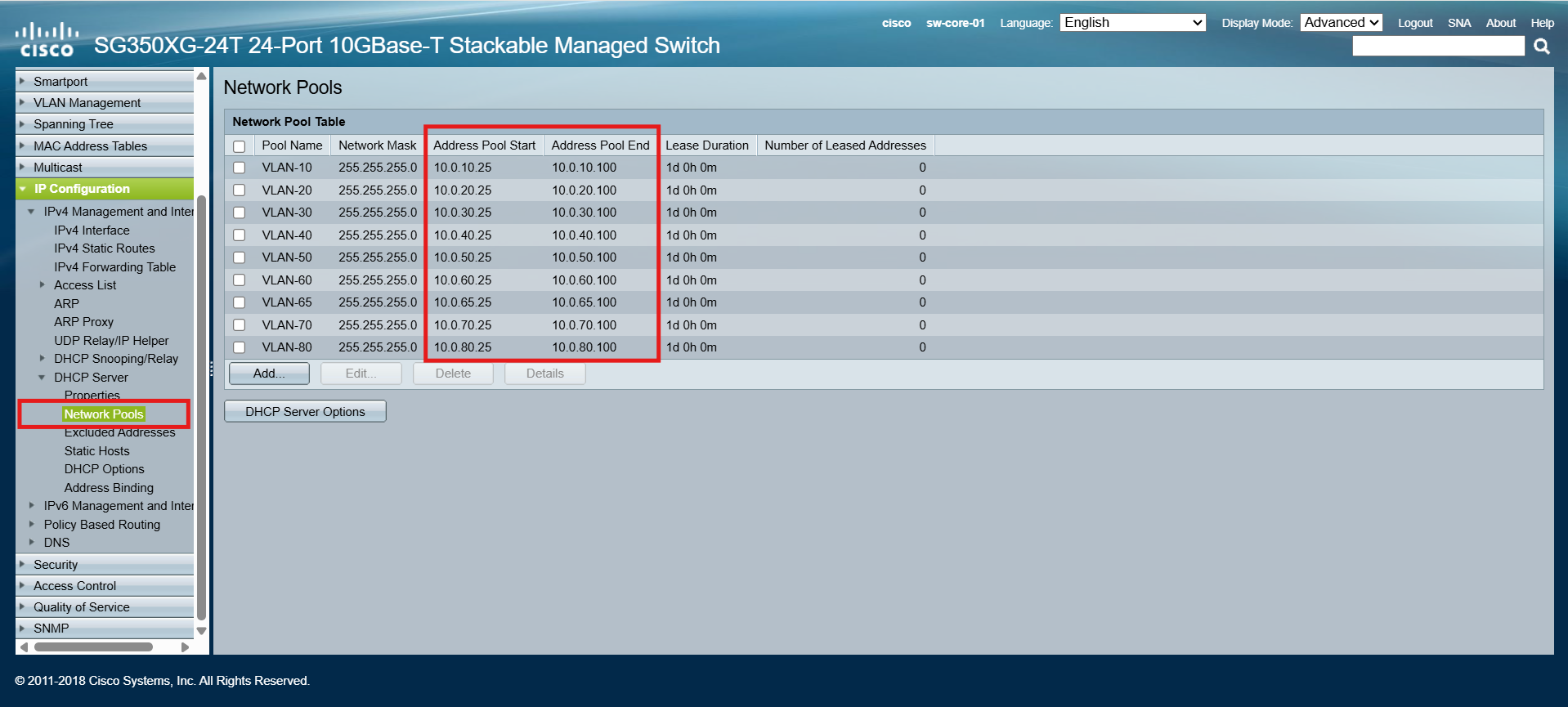
This allocation provides more than enough room for my home lab, where the number of active devices is relatively small. As the lab grows and new workloads are introduced, I can easily adjust the pool sizes or expand the ranges as needed.
💡 Best Practice: Reserve the Lower IP Range
To keep things organized and consistent, I reserved the lower portion of each subnet (for example, .1 through .24) for static assignments such as:
- Default gateways (SVIs)
- Core infrastructure (switches, firewalls, storage, hypervisors)
- Critical servers (Active Directory, DNS, monitoring)
By keeping statics and dynamics separated, it’s much easier to document, avoid conflicts, and track allocations in tools like NetBox.
Next, I switched to the CLI to configure the new Default/Black Hole VLAN (99). While VLAN 1 cannot be deleted or renamed (it’s locked into the firmware by Cisco), it can be pruned from trunk ports and removed from access ports. This effectively neutralizes VLAN 1 so that no traffic flows over it.
Because these changes are more efficient to implement via the CLI, I used the following series of commands:
!
! Cisco SG350XG Core Switch - VLAN 99 Black Hole & Trunk Configuration
! Hostname: sw-core-1
!

! Enter configuration mode
configure terminal

! Create VLAN 99
vlan database
 vlan 99
exit

! (Optional) Name VLAN 99 for clarity
interface vlan 99
 name BLACKHOLE
exit

! Assign VLAN 99 as default for access ports (te1/0/1 - te1/0/24)
interface range te1/0/1-24
 switchport mode access
 switchport access vlan 99
exit

! Configure trunk uplink to the MDF EDGE Switch (sw-edge-01)
! [Port 12 - SPF+]
interface te1/0/12
 switchport mode trunk
 switchport trunk native vlan 99
 switchport trunk allowed vlan none
 switchport trunk allowed vlan add 10,99
 switchport trunk allowed vlan remove 1
exit

! Configure trunk uplink to the MDF ACCESS Switch (sw-access-01)
! [Port 24 - RJ45]
interface te1/0/24
 switchport mode trunk
 switchport trunk native vlan 99
 switchport trunk allowed vlan none
 switchport trunk allowed vlan add 10,20,30,40,50,60,65,70,80,99
 switchport trunk allowed vlan remove 1
exit

! Exit configuration mode
exit

! Save configuration
copy running-config startup-config
⚙️ Note on OS Differences
The Cisco SG350XG does not run traditional Cisco IOS. Instead, it uses a Cisco Small Business firmware (SG300/SG350 series CLI), which looks similar to IOS but has some important differences:
- Save Command
- IOS:
write memoryorwr mem - SG350XG:
copy running-config startup-config
- IOS:
- Interface Naming
- IOS (Catalyst):
GigabitEthernet1/0/1 - SG350XG:
te1/0/1(for Ten Gigabit Ethernet ports)
- IOS (Catalyst):
- VLAN Configuration
- IOS:
vlan 99is defined in global config. - SG350XG: VLANs are created in a separate
vlan databasemode.
- IOS:
- Feature Availability
- SG350 series has fewer advanced IOS features (e.g., limited routing protocols, no EIGRP/OSPF), but it still provides Layer 3 static routing, ACLs, and VLAN management.
These differences mean that while the CLI feels familiar, it’s not 1:1 with Catalyst IOS — so commands you may find in generic Cisco documentation might need adjusting when working with the SG350XG.
| Feature / Task | Cisco IOS (Catalyst/IOS-XE) | Cisco SG350XG (Small Business) |
|---|---|---|
| Save configuration | write memory / wr mem |
copy running-config startup-config (from privileged EXEC) — same effect as boot config running-config. (Cisco) |
| Interface naming | Full: GigabitEthernet1/0/1, TenGigabitEthernet1/0/1 — Shorthand works: gi1/0/1, te1/0/1 |
Uses gi (GigE models) and te (10G models), e.g., te1/0/1; CLI explicitly documents gi and te forms. |
| VLAN creation | vlan 99 (global config) |
vlan database → vlan 99 (separate VLAN config mode). (Cisco) |
| Banner configuration | banner motd^…^, banner login^…^, banner exec^…^ |
Same banner commands supported in the business CLI / GUI. (Cisco) |
| Trunk pruning (VLAN 1) | switchport trunk allowed vlan remove 1 (plus add/explicit lists) |
Same style of switchport trunk allowed vlan add/remove supported on SMB series. (Cisco) |
| Routing features | Full suite (OSPF/EIGRP/BGP/RIP, etc.) | Static IPv4/IPv6 + RIP v1/v2; no OSPF/EIGRP/BGP. (Cisco) |
| Management options | Console/SSH CLI, HTTPS GUI (IOS-XE), SNMP, NETCONF/RESTCONF | Console/SSH CLI, HTTPS Web GUI, SNMP (no NETCONF/RESTCONF). (Cisco) |
Enabling Access via Management VLAN (10)
Thus far, I have been accessing the GUI and CLI via the dedicated OOB Management Port. The port is physically separate from the switching/routing fabric. It has its own independent IP address and cannot be assigned to a VLAN. it’s designed for direct management access even if the production network is down.
To manage the switch through VLAN 10—rather than being directly tethered to the out-of-band (OOB) management port—I assigned Port 1 to VLAN 10. With this configuration in place, the GUI becomes accessible via the SVI gateway IP address (10.0.10.1) that I defined earlier when creating the VLANs:
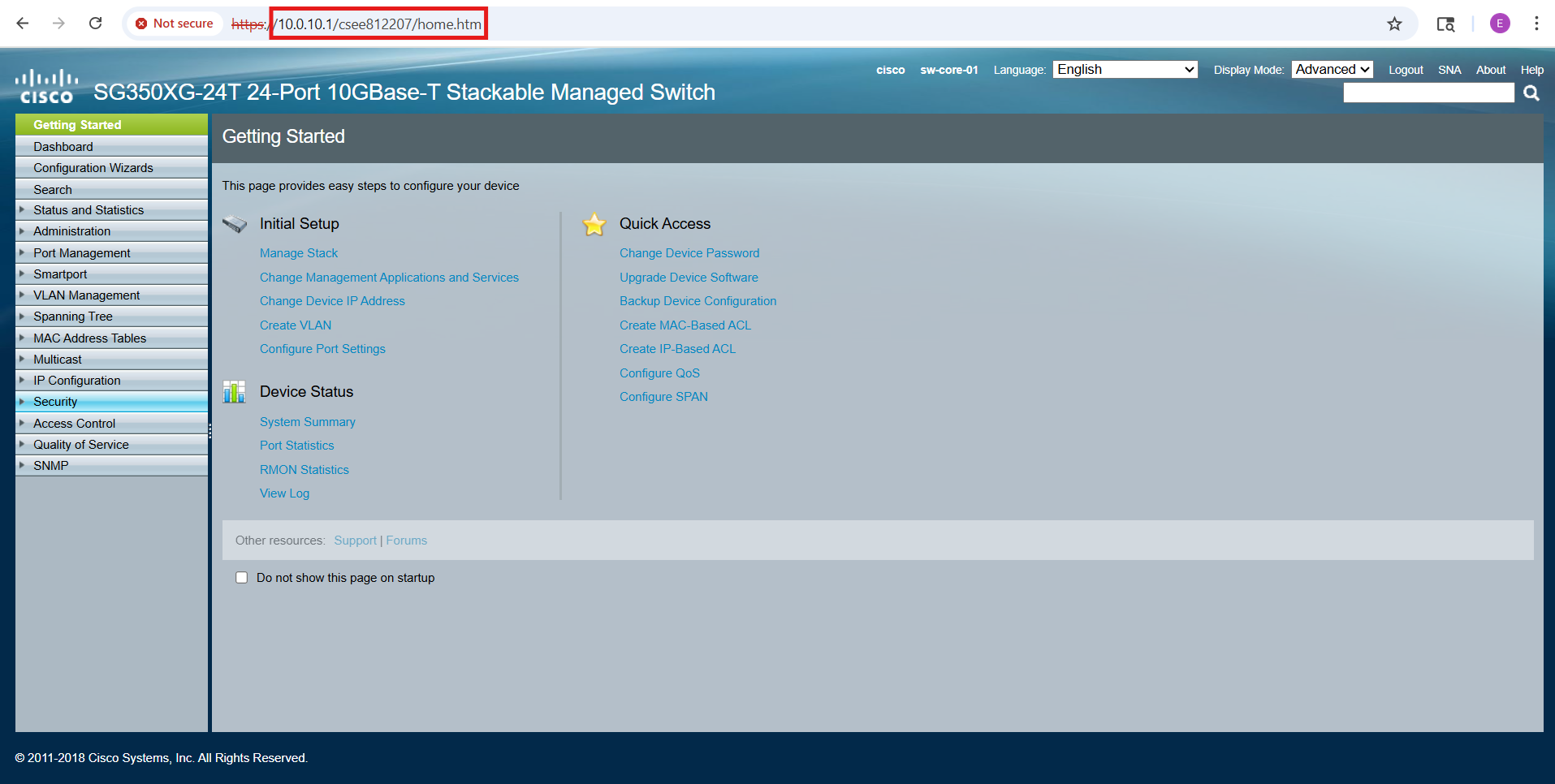
This approach allows me to route and control access to the management interface over the network itself, providing more flexibility while still maintaining separation between production traffic and switch management.
Edge Switch (FS S3900-24F4S-R) Configuration
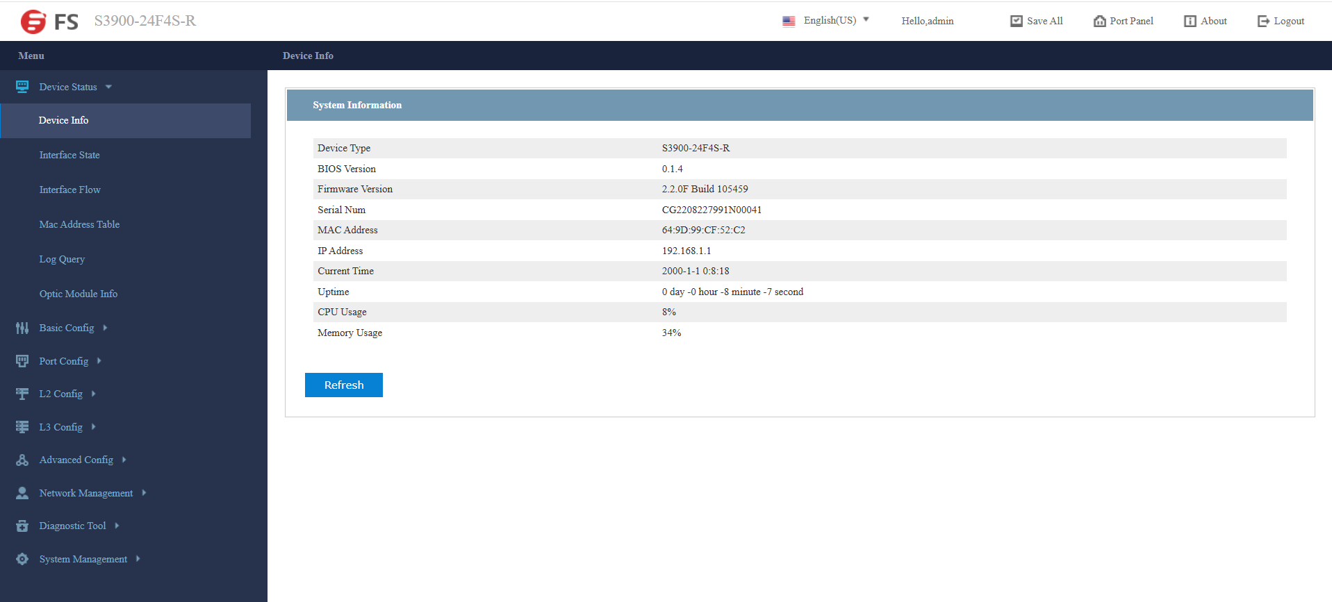
In addition to its CLI, the FS S3900 series provides a convenient web-based GUI for management. Out of the box, the switch’s GUI is accessible via HTTP on the default management IP address (192.168.1.1), and any Ethernet port can be used for initial access. To connect, I configured my laptop’s NIC with a compatible IP address (192.168.1.2) and opened the GUI in a browser:
The very first task after logging in is to replace the default credentials. Default usernames and passwords are widely known and pose a major security risk if left unchanged.
- Navigate to: System Management → User Management → User Management.
- Select the
adminaccount and set a strong new password.
The Hostname was also updated to match the name assigned in the NetBox database:
- Navigate to: Basic Config → Hostname.
- Update the Hostname to: sw-edge-01.
Transit VLANs
The eight RJ45 ports on the FS switch are dedicated to forming two transit VLANs between the ISP CPE equipment (AT&T BGW320-505 and the future Comcast gateway) and the two firewalls (FortiWiFi 61F and Meraki MX68W).
- Ports 1–4 are assigned to VLAN 101.
- Ports 5–8 are assigned to VLAN 102.
To keep the configuration clear and maintain accurate documentation, I also used the Port Description fields in the FS switch GUI to label each connection. This way, the physical port assignments are immediately visible in both the GUI and CLI, reducing the chance of error when reviewing or troubleshooting the design:
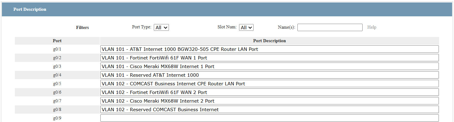
I used the GUI to define the transit VLANs (L2 Config → VLAN Config.), as shown below:
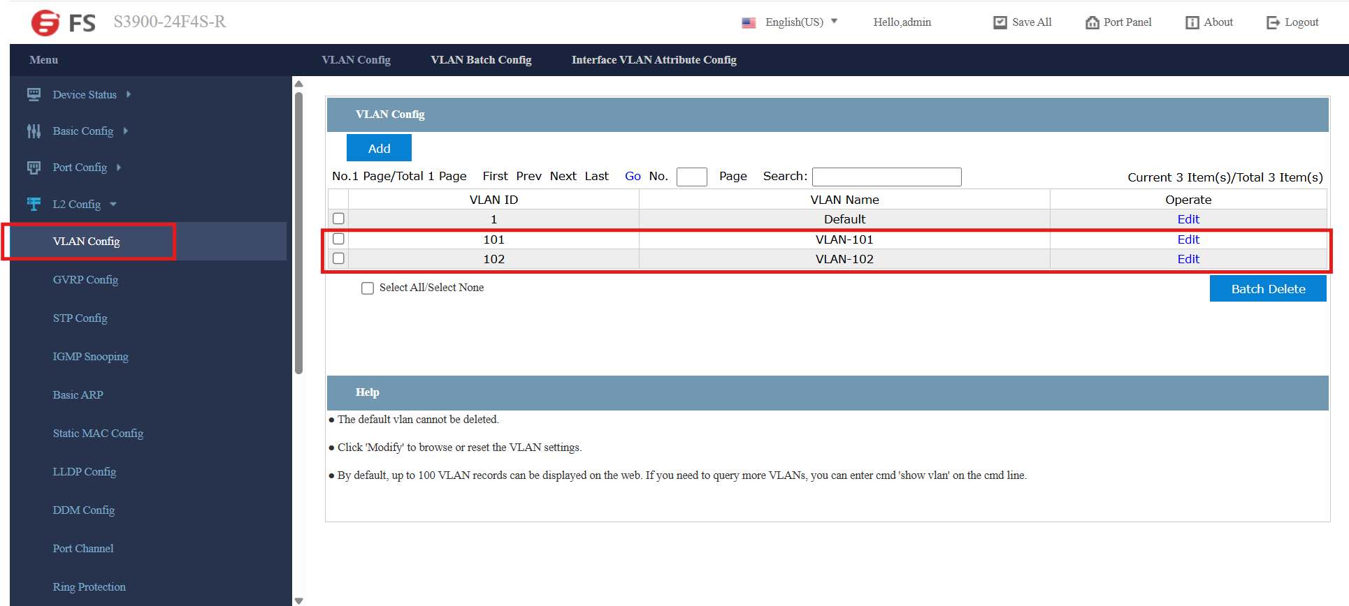
The FS web GUI feels a bit clunky, but I was able to successfully assign the transit VLANs to the eight RJ45 ports.
⚠️ Important Note: After reassigning a port to one of the new VLANs, there is no associated SVI for GUI access. By default, only VLAN 1 is mapped to the management interface (192.168.1.254). I learned this the hard way 😅. Initially, I had my laptop connected to Port 1, and when I reassigned that port to VLAN 101, my GUI session dropped instantly.
Fortunately, since the change was unsaved, I was able to power-cycle the switch and re-establish the connection through VLAN 1. To avoid this issue moving forward, I connected through an SFP port (Port 24) with an RJ45 adapter, which allowed me to complete the configuration of the designated transit VLAN ports without losing management access.
Enabling Access via Management VLAN (10)
Up to this point, I’ve been managing the switch exclusively through the default SVI on VLAN 1 (192.168.1.1), which provides both GUI and CLI access.
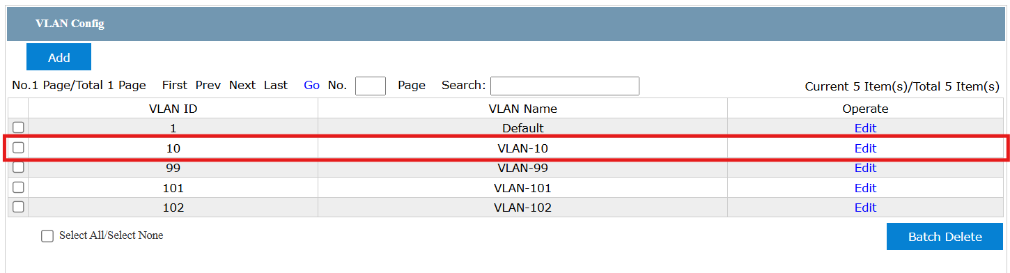
To enable management from anywhere in the network—rather than being tied to VLAN 1—I extended VLAN 10 to the edge switch and configured it as the dedicated management VLAN. This allows the switch to be administered securely over the production network, while keeping management traffic logically separated from user and server traffic:
⚠️ Fallback Access: As an added safeguard, I configured Port 24 to remain in VLAN 1. This ensures I still have a direct management path in the event of a network outage or misconfiguration on VLAN 10. Having a dedicated fallback port helps avoid lockouts and provides a reliable recovery option, which is particularly important when experimenting in a lab environment.
The following CLI commands were issued on the FS edge switch to configure trunk and access ports to effectively neutralize VLAN 1 by designating VLAN 99 as the default black hole VLAN:
! Enable privileged command mode
enable

! Enter configuration mode
config

! Create the VLAN 10 SVI for in-band management
interface vlan 10
 ip address 10.0.10.2 255.255.255.0
 no shutdown
exit

! Configure trunk uplink to the MDF CORE Switch (sw-core-01)
! [Port 25 - SPF+]
interface tg0/25
 switchport mode trunk
 switchport trunk vlan-allowed none
 switchport trunk vlan-allowed add 10,99
 switchport trunk vlan-allowed remove 1
 switchport trunk vlan-untagged none
 switchport trunk vlan-untagged add 99
 switchport pvid 99
exit

! Make unused/access ports dump untagged frames into VLAN 99 (black hole)
! (skip transit ports (1 - 8) and trunk/uplink (24))
interface range ethernet 0/9-23
 switchport mode access
 switchport pvid 99
exit


! Exit configuration mode
exit

! Save configuration
write all

! Exit privileged command mode
exit
⚙️ Note on OS Differences
Just as with the Cisco core switch, the syntax is similar to the Cisco IOS Catalyst CLI, but with slight variations specific to the FS S3900 platform:
| Task | Cisco IOS Catalyst CLI | FS S3900 CLI |
|---|---|---|
| Create VLAN | vlan 99 (global config) |
vlan database → vlan 99 |
| Assign access VLAN | switchport access vlan 99 |
Same syntax, but prefixed with interface ethernet instead of interface gi/te |
| Management SVI | interface vlan 10 + ip address … |
Same, but FS often requires no shutdown explicitly |
| ACL creation | ip access-list extended MGMT-ACL → permit/deny rules |
Same syntax |
| Apply ACL to VLAN | ip access-group MGMT-ACL in |
Same syntax |
| Enable HTTPS | ip http secure-server |
server https enable |
| Enable SSH | ip ssh version 2 + crypto key generate rsa |
ip ssh server enable (keys generated automatically on first enable) |
MDF Access Switch (Cisco Catalyst 1000-48P-4G-L) Configuration
The Cisco Catalyst 1000 series includes a convenient web-based GUI for management. Out of the box, the GUI is accessible via HTTP/HTTPS on the switch’s native VLAN (VLAN 1) SVI address.
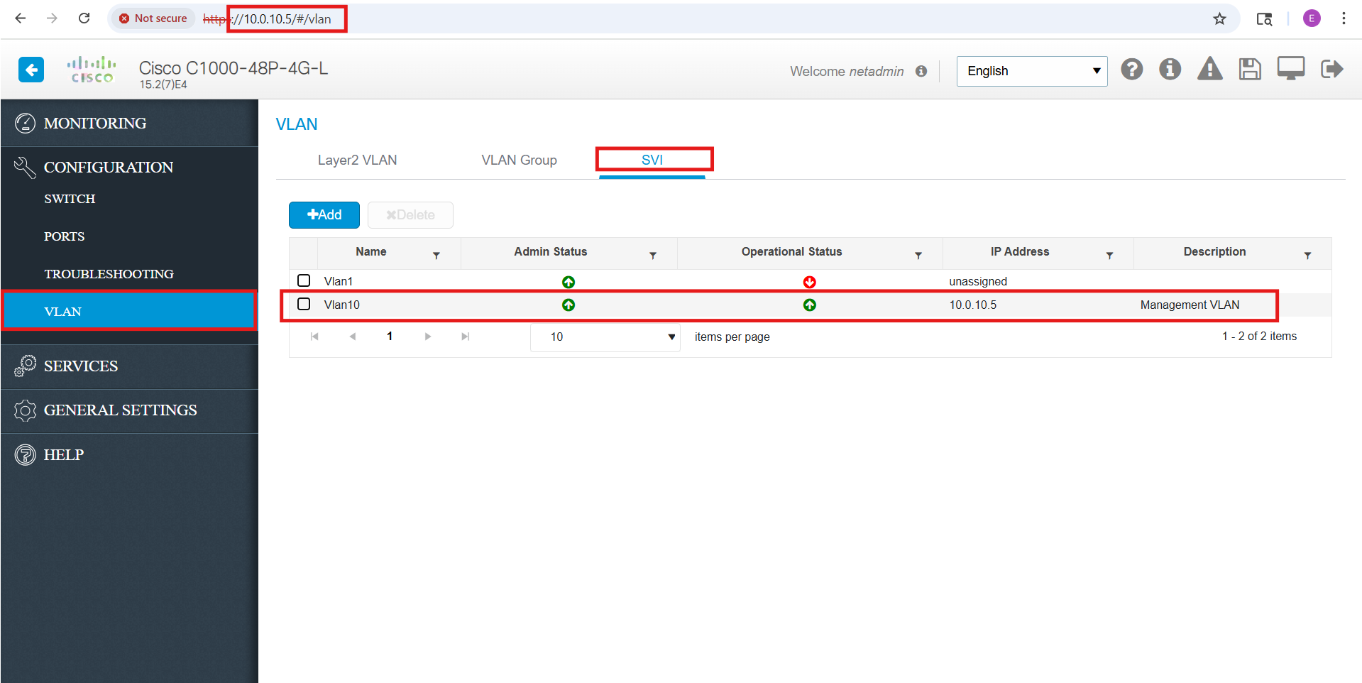
As part of my security hardening, I disabled the default/native VLAN 1 (192.168.1.254) and extended my dedicated Management VLAN (10) instead. After assigning an IP address to the VLAN 10 SVI, I was able to successfully connect to the switch’s GUI through the new management interface (10.0.10.5):
While the web GUI includes a built-in CLI, it feels awkward and limited compared to working in a traditional SSH session. For the remaining configuration tasks, SSH provides a much more efficient and reliable way to interact with the switch.
Out of the box, SSH support is present, but the CLI is not actually accessible until SSH is fully initialized. To enable remote SSH access, I entered the following commands:
ip domain-name edbradleyweb.local
crypto key generate rsa modulus 2048
ip ssh version 2
line vty 0 4
 transport input ssh
 login local
exit
username netadmin privilege 15 password **************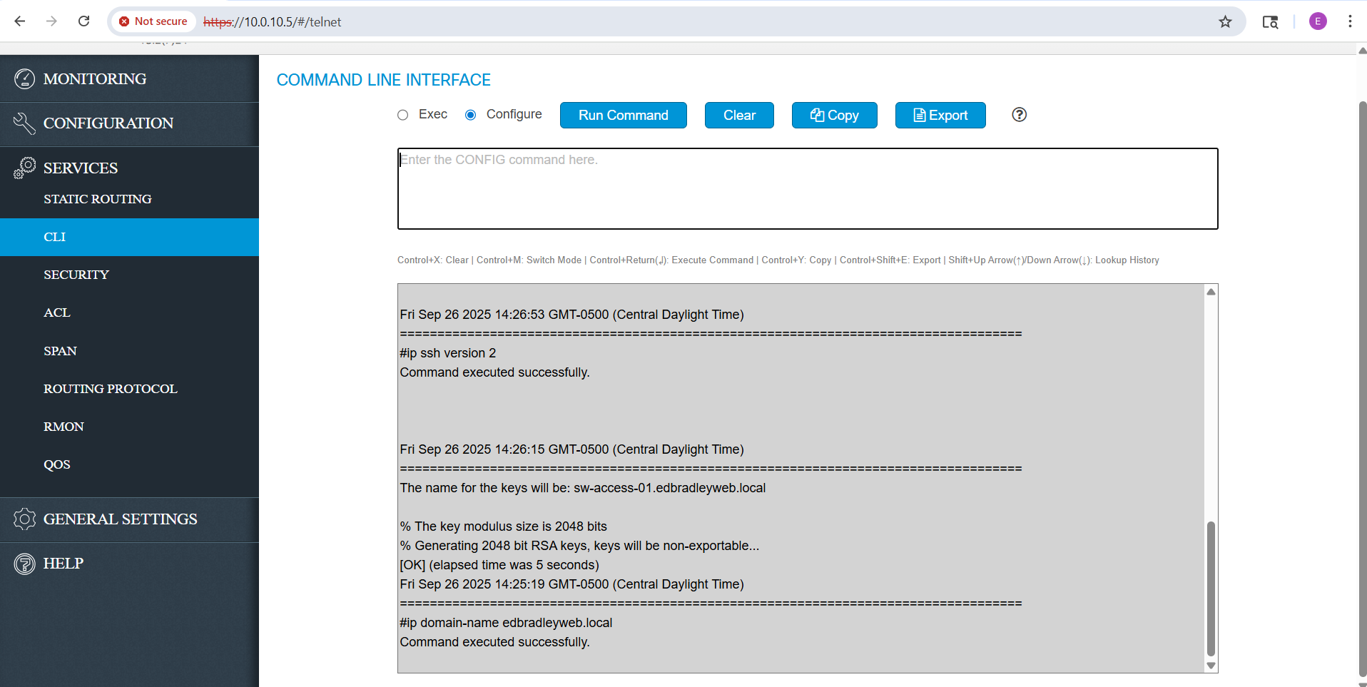
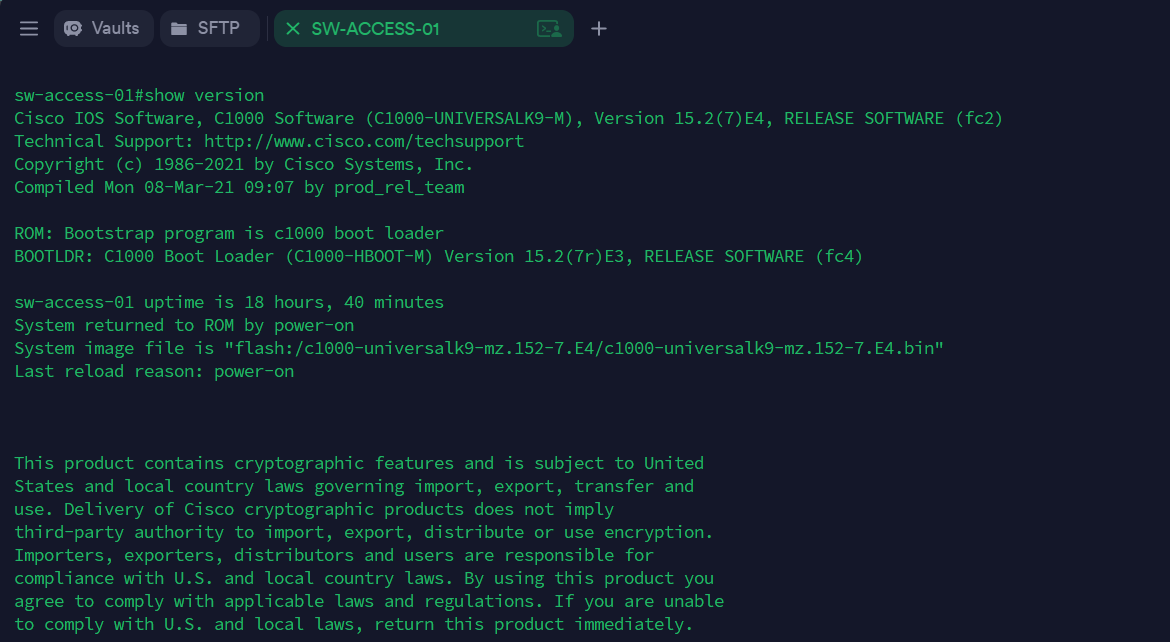
Once SSH was initialized, I was able to connect to the switch via the VLAN 10 SVI (using Terminus as my SSH client):
From there, I extended the other local VLANs to this switch, and assigned a default gateway (the Core Switch), using the CLI commands below:
configure terminal

! Define all VLANs (except VLAN 10, which already exists) ---
vlan 20
 name SERVERS
vlan 30
 name WORKSTATIONS
vlan 40
 name PRINTERS
vlan 50
 name DMZ
vlan 60
 name SECURED-WIFI
vlan 65
 name GUEST-WIFI
vlan 80
 name IOT
vlan 99
 name BLACKHOLE
exit
!
! Define default gateway (Core Switch)
ip default-gateway 10.0.10.1
Next, I assigned VLAN 99 as the default for all unused access ports, ensuring that any untagged or rogue traffic is dropped into a black-hole VLAN:
! --- Assign VLAN 99 as default on unused access ports ---
! (except port 1 -VLAN 10- - being used for initial management)
interface range GigabitEthernet1/0/2-0-48
 switchport mode access
 switchport access vlan 99
exit
After that, I configured the uplink ports as trunks and pruned VLAN 1 from them, effectively neutralizing the native VLAN:
! Configure trunk uplink to the MDF CORE Switch (sw-core-01)
! [Port 47 - RJ45]
interface gi1/0/47
 switchport mode trunk
 switchport trunk allowed vlan none
 switchport trunk allowed vlan add 10,20,30,40,50,60,65,70,80,99
 switchport trunk allowed vlan remove 1
 switchport trunk native vlan 99
exit

! Configure trunk uplink to the IDF ACCESS Switch (sw-access-03)
! [Port 49 - SPF]
interface gi1/0/49
 switchport mode trunk
 switchport trunk allowed vlan none
 switchport trunk allowed vlan add 10,20,30,40,50,60,65,70,80,99
 switchport trunk allowed vlan remove 1
 switchport trunk native vlan 99
exit
IDF Access Switch (Cisco CBS220-24T-4G) Configuration
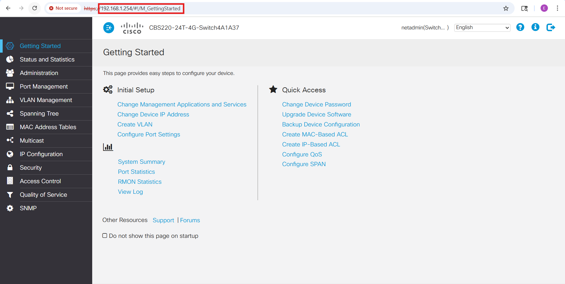
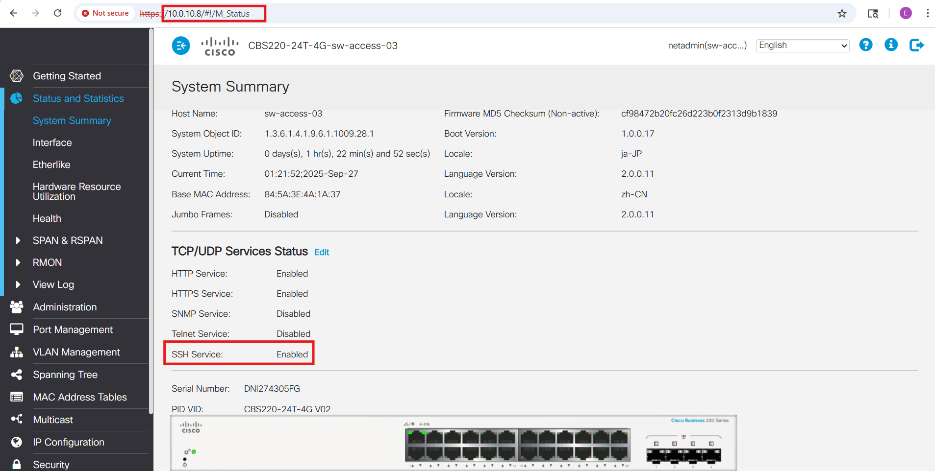
The Cisco CBS220 series includes a convenient web-based GUI for management. Out of the box, the GUI is accessible via HTTP/HTTPS on the switch’s native VLAN (VLAN 1) SVI address:
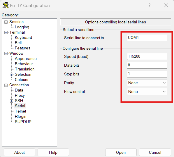
I began by enabling SSH access through the web interface (Security → TCP/UDP Services). Unlike the C1000 series, the CBS220 does not provide an embedded CLI within the GUI. To avoid the risk of locking myself out while changing the management VLAN and SVI settings, I switched to a direct console connection. Using PuTTY with a USB-to-serial adapter (configured for 115200 baud, 8 data bits, no parity, 1 stop bit, and no flow control), I was able to manage the switch independently of the network and safely apply the initial configuration:
From the console, I entered the necessary commands to enable both the web GUI (HTTPS) and the CLI (SSH) over VLAN 10:
!
! Set the host name
!
hostname sw-access-03
!
! Extend VLAN 10 to this switch
!
vlan 10
  name MANAGEMENT
exit
!
! Set VLAN 10 as the management VLAN
!
management-vlan vlan 10
!
! Set the SVI IP address for the new management VLAN
! For GUI (Web) & CLI (SSH) access over the network
!
management vlan ip-address 10.0.10.8 mask 255.255.255.0
!
! Set the default gateway address (core switch)
!
ip default gateway 10.0.10.1
!
! Assign Port 1 to VLAN 10 (for Laptop access via Network cable)
!
interface gi1
 switchport mode access
 switchport access vlan 10
exit
Cisco CBS220 Console Connection Commands
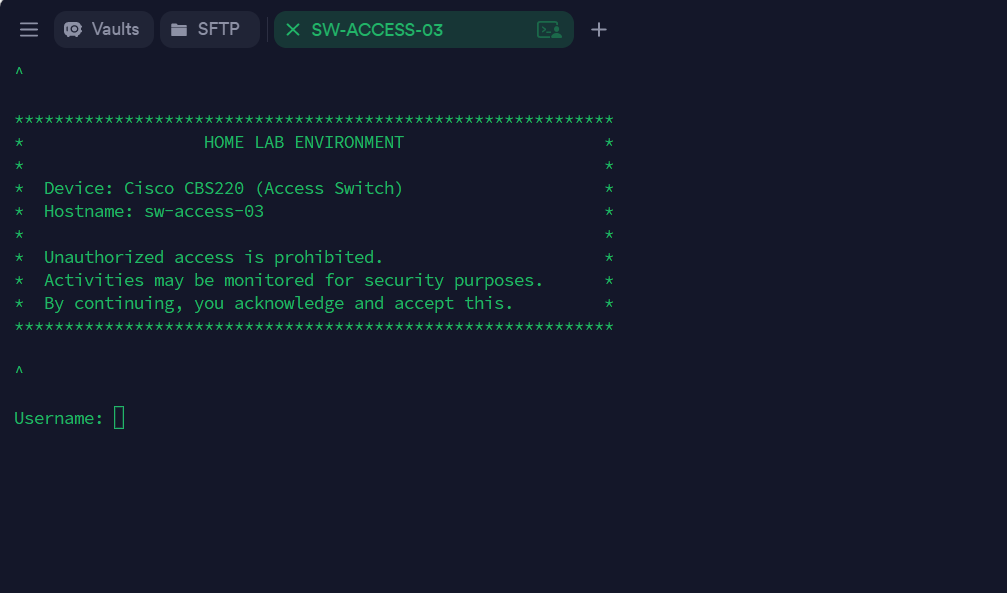
Once these settings were in place, I adjusted the IP configuration on my laptop and successfully accessed the switch via both the GUI and SSH through the VLAN 10 subnet (10.0.10.0/24):
Next, I extended the remaining local VLANs, designated VLAN 99 as the Black Hole VLAN (the new default for untagged or rogue traffic), and neutralized VLAN 1 by pruning it from all trunk ports:
configure terminal

! --- Extend all local VLANs with names ---
vlan 20
 name SERVERS
exit
vlan 30
 name WORKSTATIONS
exit
vlan 40
 name PRINTERS
exit
vlan 50
 name DMZ
exit
vlan 60
 name SECURED-WIFI
exit
vlan 65
 name GUEST-WIFI
exit
vlan 70
 name BACKUP-TRAFFIC
exit
vlan 80
 name IOT
exit
vlan 99
 name BLACKHOLE
exit

! --- Set VLAN 99 as the default VLAN (for untagged traffic) ---
vlan default-vlan 99
! NOTE: this takes effect after a reboot

! --- Neutralize VLAN 1 ---
! Do not use VLAN 1 on access ports
interface range gi2-23
 switchport mode access
 switchport access vlan 99
exit


! Configure trunk uplink to the MDF ACCESS Switch (sw-access-01)
! [Port 25 - SPF+]
interface gi25
 switchport mode trunk
 switchport trunk allowed vlan add 10,20,30,40,50,60,65,70,80,99
 switchport forbidden vlan add 1
 switchport trunk native vlan 99
exit

end

! SAVE SETTINGS!
write
⚙️ Note on OS Differences
Again, although the CBS220 supports a familiar Cisco-style CLI, its command set is not identical to traditional IOS or IOS-XE. Instead, it runs a lighter “Cisco Business OS” that blends IOS-like syntax with Small Business switch conventions. For example, VLANs are created directly with the vlan <id> command (rather than through the old vlan database mode), and management plane restrictions are handled with management access-list / management access-class instead of the standard IOS ip access-group method. Likewise, some interface commands such as switchport general and switchport forbidden vlan are unique to the CBS220 series. While the workflow feels familiar to IOS users, it’s important to keep these differences in mind to avoid confusion when moving between Catalyst enterprise gear and CBS220 switches.
| Task | Traditional Cisco IOS / IOS-XE | CBS220 CLI (Cisco Business OS) | Notes |
|---|---|---|---|
| Create VLAN | vlan 20 name SERVERS |
vlan 20 name SERVERS |
Similar syntax, but CBS220 doesn’t support legacy vlan database mode. |
| Assign port to VLAN (access) | interface gi1/0/5 switchport mode access switchport access vlan 20 |
Same syntax as IOS | Works the same way as enterprise IOS. |
| Configure trunk port | interface gi1/0/24 switchport mode trunk switchport trunk allowed vlan 10,20,30 |
Same, but also supports switchport forbidden vlan add/remove |
CBS220 adds the “forbidden VLAN” concept, not found in IOS. |
| Set native VLAN on trunk | switchport trunk native vlan 10 |
Same command | Both support setting a native VLAN (untagged). |
| Create SVI (Layer 3 VLAN intf) | interface vlan 10 ip address 10.0.10.1 255.255.255.0 |
Same syntax | CBS220 supports SVIs for mgmt but is not a full L3 switch. |
| Default VLAN change | Not supported (VLAN 1 is always default/native unless pruned) | vlan default-vlan 99 |
CBS220 allows changing the global “default VLAN” (after reboot). |
| Management VLAN | No dedicated command; mgmt IP is tied to whichever SVI you configure | management-vlan 10 |
CBS220 has an explicit command to designate the mgmt VLAN. |
| SSH enablement | crypto key generate rsa ip ssh version 2 line vty 0 4 |
ip ssh server |
CBS220 simplifies SSH enablement; keys are auto-handled. |
| Restrict management access | ip access-list standard MGMT permit host 10.0.10.101 line vty 0 4 → access-class MGMT in |
management access-list MGMT_ONLY permit ip 10.0.10.101/32 service sshmanagement access-class MGMT_ONLY |
CBS220 has a dedicated “management access-list” feature. |
Desktop Access Switch (Cisco Meraki MS120-8FP) Configuration
The Meraki MS120-8FP is managed entirely through the Meraki Dashboard, so it requires an active internet connection from the very beginning. I’ve had this switch for some time, and it’s already registered in my Dashboard, where it’s still connected to my “old” lab environment:
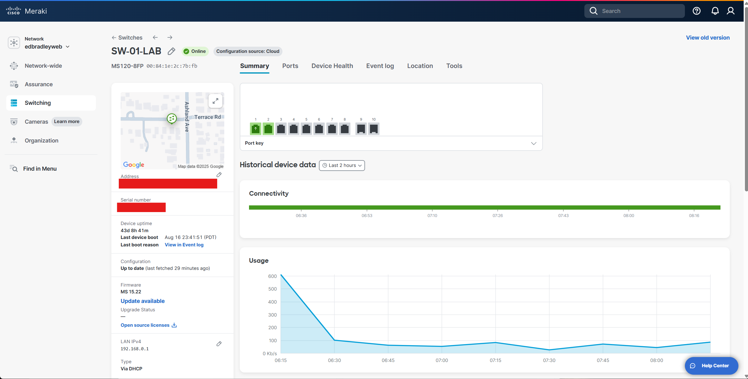
At the moment, I’m not quite ready to disconnect it completely, since I still have a workstation and another legacy switch running through it. I plan to wrap up those “loose ends” before my next post.
In the meantime, I’ve started preparing the MS120 for integration into the new lab environment by staging the trunk connections on both sides.
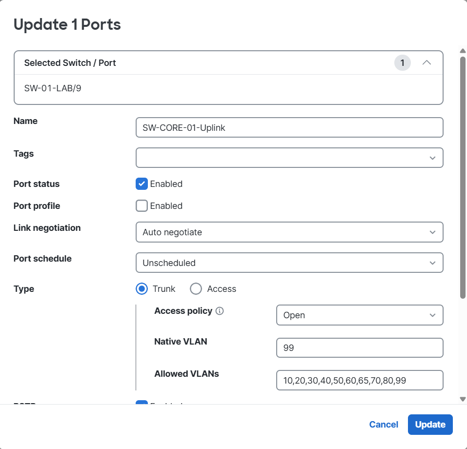
On the core switch, I configured an additional uplink port (23) as a trunk, following the same pattern I used with the other access switches:
! Configure trunk uplink to the Desktop ACCESS Switch (sw-access-02)
! [Port 23 - RJ45]
interface te1/0/23
 switchport mode trunk
 switchport trunk native vlan 99
 switchport trunk allowed vlan none
 switchport trunk allowed vlan add 10,20,30,40,50,60,65,70,80,99
 switchport trunk allowed vlan remove 1
exit
On the MS120, I staged its uplink configuration in the Dashboard, so it’s ready to connect once I cut over from the old setup:
By the time I publish my next update, the MS120-8FP should be fully migrated and serving as a PoE-enabled access switch within the new VLAN-segmented lab network.
Wrapping Up
With the core switching fabric in place, I now have the foundational network structure for my home lab: VLAN segmentation is defined, inter-VLAN communication is working as designed, and trunk links are extending those VLANs across the access layer. This sets the stage for the next critical step—integrating the firewalls and establishing secure connectivity to the Internet. In my upcoming post, I’ll focus on bringing the FortiWiFi 61F and Meraki MX68W into the design, implementing policies, and ensuring the new lab operates with both flexibility and strong security controls.
👉 Next up: Integrating the firewalls and bringing the new lab online. It’s time to connect to the internet securely and see this segmented network in action.