
Ed Bradley’s Web: Weaving Networks, Security, Cloud, and Code.
Introduction
Now that the switch fabric is in place, the next step is to integrate and configure the firewalls to provide secure internet access for the new lab network. In enterprise and SMB environments, two popular firewall platforms are Fortinet and Cisco Meraki. For my lab, I have “entry-level” models from both product lines:
- Fortinet FortiWiFi 61F
- Cisco Meraki MX68W
Both appliances are more than adequate for a home lab, and I’ll be running them side by side to test and experiment with independently.
Another advantage of this setup is that both firewalls include built-in WiFi radios. This allows me to experiment with wireless access and security features without needing to purchase and deploy a separate standalone access point. Having integrated wireless in both the FortiWiFi 61F and the Meraki MX68W gives me the flexibility to test different scenarios — from secure SSID deployments and VLAN integration to wireless security policies.
From my professional experience, I tend to favor the Fortinet line of firewalls. I think they deliver a better "bang for the buck", when it comes to throughput, connectivity options, and straight-forward configuration. In contrast, Meraki appliances excel in cloud-based management and provide robust visibility and ease of use, but that convenience comes with the well-known “Meraki Tax.” Without an active license subscription, a Meraki firewall becomes effectively unusable. While the Meraki Dashboard is modern and visually appealing, the latency of some operations can be frustrating at times.
The FortiWiFi 61F, on the other hand, continues to operate even without a subscription. However, to receive ongoing FortiOS firmware updates and security feature enhancements, a basic subscription is required — typically costing about half the price of a comparable Meraki license. Given today’s rapidly evolving threat landscape, keeping firewall firmware and signatures current isn’t just best practice — it’s essential for maintaining a secure network perimeter.
Below is a quick comparison of the two platforms:
🔍 FortiWiFi 61F vs. Cisco Meraki MX68W
| Feature / Aspect | Fortinet FortiWiFi 61F | Cisco Meraki MX68W |
|---|---|---|
| Form Factor | Compact desktop firewall with integrated WiFi | Compact desktop firewall with integrated WiFi |
| Management Style | Local GUI/CLI + FortiCloud (optional) | 100% cloud-managed (Meraki Dashboard) |
| Licensing | Base license includes firmware/security updates with FortiCare support | Mandatory subscription (“Meraki License”) for functionality; device unusable without it |
| Security Features | NGFW features (UTM, IPS, AV, web filtering) with add-on licenses; flexible | Cloud-delivered IPS/IDS, content filtering, AMP (with license) |
| Performance (throughput) | ~1 Gbps firewall throughput; ~700 Mbps NGFW | ~450 Mbps firewall throughput; ~200 Mbps with advanced features |
| Ease of Use | Straightforward configuration, rich CLI; steeper learning curve for advanced features | Extremely simple to set up and manage via Dashboard; minimal CLI |
| Cost / Value | Strong “bang for the buck,” especially without UTP bundle | Higher ongoing cost due to licensing (“Meraki Tax”) |
| Best Fit | Labs, SMBs, power users wanting flexibility & control | SMBs or enterprises prioritizing easy centralized management |
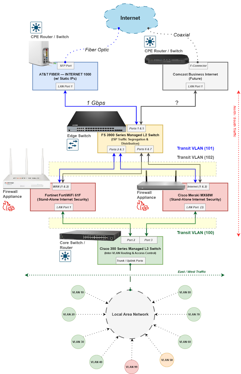
Below is a high-level diagram of the network perimeter, showing how the two firewalls will be integrated into the new lab design. I currently have AT&T Fiber as my primary Internet service and plan to add Comcast Business Internet in the future, so that path is included as a placeholder in the design.
The FS3900 switch sits at the very edge of the network perimeter and distributes Internet connectivity across both firewalls. Two dedicated Transit VLANs (101 and 102) are used to segregate traffic from each ISP. From there, traffic flows through another Transit VLAN (100) into the Core Switch, where it is routed into the internal LAN.
To provide flexibility, I will implement Policy-Based Routing (PBR) on the Core Switch, allowing me to steer traffic through either firewall as needed. In addition, I plan to enable SD-WAN features on both firewalls to provide failover and load balancing between the two Internet circuits:
Deploying the Cisco Meraki MX68W
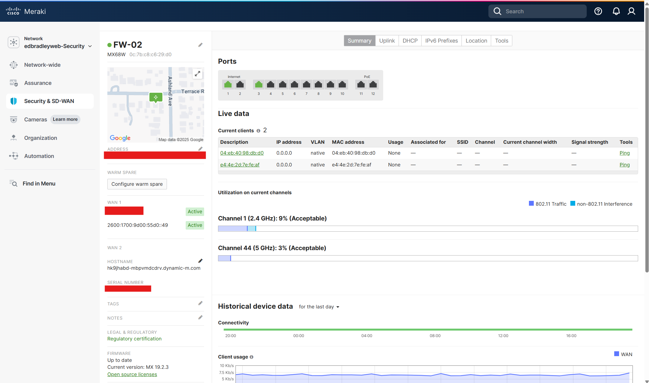
The MX68W is already registered with the Meraki Dashboard. Internet access is required to manage the Firewall. So, I connected the Internet 1 port on the Firewall the one of the AT&T CPE router's LAN ports. As shown below, the Firewall can now be monitored and configured, via the cloud:
Next, I created a pathway from the internal LAN to the Internet, via the MX68W, using the Transit VLAN (100) and Port 3 on the Core Switch (Cisco SG350XG) as the uplink.
Core switch Port 3 Configuration:
I configured Port 3 on the core switch as a trunk port that tags VLAN 100 (and applies the standard native VLAN (99) and VLAN 1 neutralization:
interface gi1/0/3
 description Uplink-to-MX68W
 switchport mode trunk
 switchport trunk allowed vlan add 100,99
 switchport trunk native vlan 99
 switchport trunk allowed vlan remove 1
exit
MX68W switch Port 3 (LAN) Configuration:
Using the Meraki Dashboard, I configured Port 3 as part of VLAN 100 (Transit). The Meraki MX platform differs from traditional firewalls like the FortiGate — instead of configuring individual physical ports directly, you define logical LAN interfaces under Security & SD-WAN → Addressing & VLANs and then map those interfaces to the appropriate physical ports.
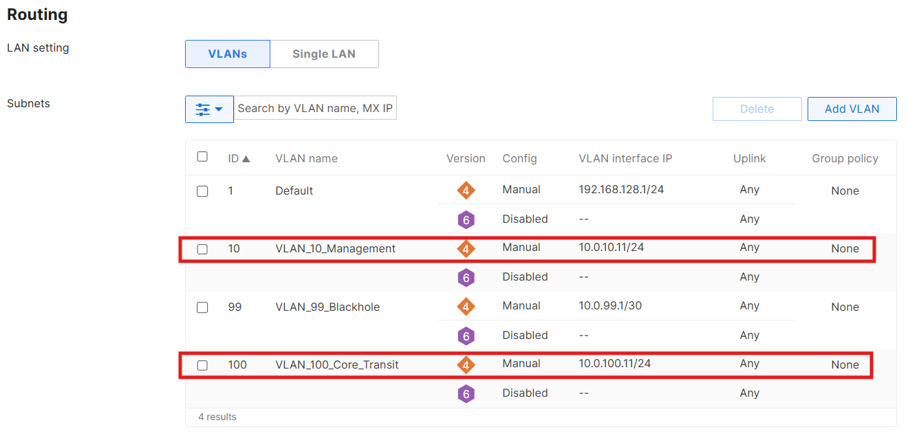
As shown below, I set the MX68W's Routing LAN setting to VLANs. Then I created the Transit VLAN (100) and assigned an IP address on the same subnet as the Core switch (10.0.100.2). Next, I configured Port 3 as a trunk port that allows only VLAN 100 traffic:
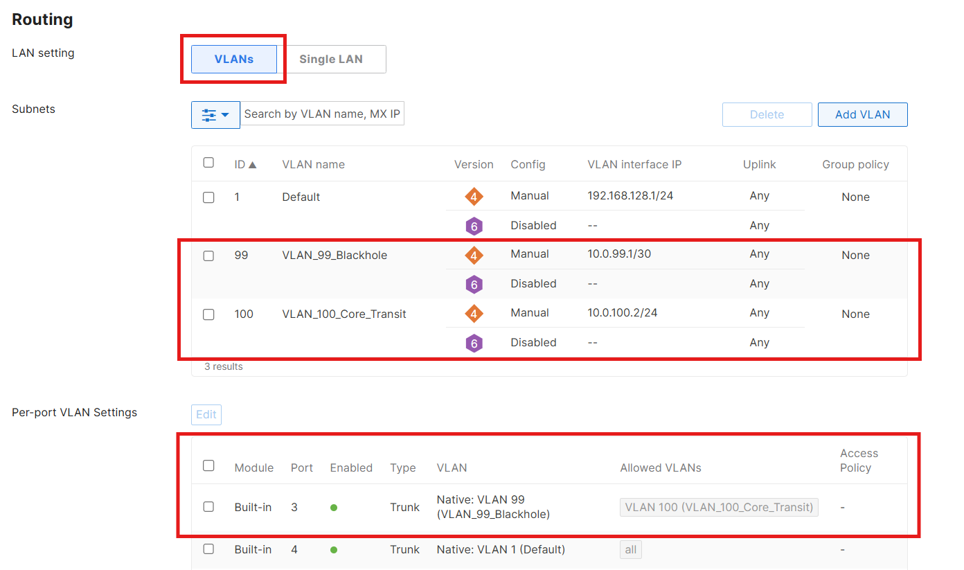
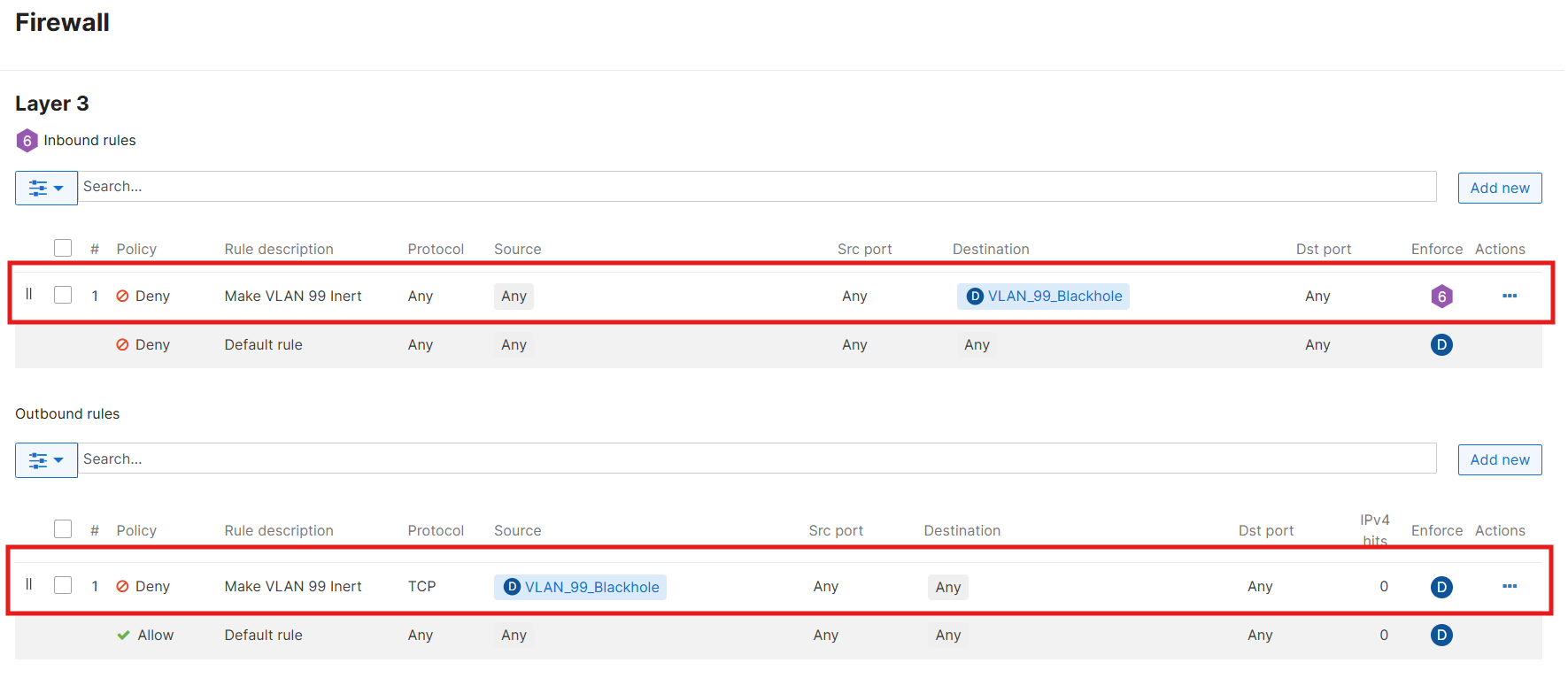
One important caveat: the Meraki Dashboard always requires a Layer-3 address when creating a VLAN. You can’t define a “tag-only” VLAN without assigning an IP. To keep things clean, I created VLAN 99 (Black Hole) on the MX with a small, unused, subnet (10.0.99.0/30). I then disabled services and blocked traffic to/from it. This satisfies the Dashboard’s requirements while ensuring that nothing in the environment actually uses that VLAN:
With this in place, I was able to reach the Internet by extending the Management VLAN (10) to the MX68W, adding it to the allowed VLANs on the transit trunk ports, and temporarily pointing my laptop’s default gateway to the MX (10.0.10.2). This worked — but it introduced a new problem: I lost access to the other VLANs, which remain reachable only through the core switch default gateway (10.0.10.1). In effect, I now had a “hard-wired” Internet path through the MX, but no visibility of my other segments.
This is exactly where Policy-Based Routing (PBR) comes in. By applying PBR rules on the core switch, I can selectively route VLAN Internet traffic through either firewall. For example, I can steer all Server VLAN (20) Internet traffic through the MX68W, while routing IoT VLAN (80) traffic through the FortiWiFi. This gives me flexibility to experiment, compare features, and simulate real-world enterprise routing designs.
Before implementing Policy-Based Routing (PBR), I decided to revisit and refine the IP addressing scheme for the firewall SVIs. I reserved the range 10.0.x.10 through 10.0.x.19 in each VLAN specifically for transit and extended firewall interfaces.
As I started mapping out the first few addresses, it became clear that this was a good opportunity to step back and establish a global addressing standard for the entire lab. Documenting this scheme up front provides consistency, avoids conflicts, and makes future expansion far easier to manage.
I find that with a new network, it’s a best practice to plan and document IP addressing schemes early in the design process. Clear, consistent allocation of subnets and reserved ranges prevents overlap, simplifies troubleshooting, and ensures future scalability. By defining standards for gateways, firewall interfaces, DHCP scopes, and static assignments up front, you create a “source of truth” that both engineers and monitoring systems can rely on.
The result is the structured addressing plan shown below:
| VLAN ID | Name | Subnet | Core (SVI) | FortiWiFi | Meraki MX | DHCP Pool | Static |
|---|---|---|---|---|---|---|---|
| 10 | Management | 10.0.10.0/24 | 10.0.10.1 | 10.0.10.10 | 10.0.10.11 | 10.0.10.25 – .100 | 10.0.10.101+ |
| 20 | Servers | 10.0.20.0/24 | 10.0.20.1 | 10.0.20.10 | 10.0.20.11 | 10.0.20.25 – .100 | 10.0.20.101+ |
| 30 | Workstations | 10.0.30.0/24 | 10.0.30.1 | 10.0.30.10 | 10.0.30.11 | 10.0.30.25 – .100 | 10.0.30.101+ |
| 40 | Printers | 10.0.40.0/24 | 10.0.40.1 | 10.0.40.10 | 10.0.40.11 | 10.0.40.25 – .100 | 10.0.40.101+ |
| 50 | DMZ | 10.0.50.0/24 | 10.0.50.1 | 10.0.50.10 | 10.0.50.11 | 10.0.50.25 – .100 | 10.0.50.101+ |
| 60 | Secure WiFi | 10.0.60.0/24 | 10.0.60.1 | 10.0.60.10 | 10.0.60.11 | 10.0.60.25 – .100 | 10.0.60.101+ |
| 65 | Guest WiFi | 10.0.65.0/24 | 10.0.65.1 | 10.0.65.10 | 10.0.65.11 | 10.0.65.25 – .100 | 10.0.65.101+ |
| 70 | Backup Traffic | 10.0.70.0/24 | 10.0.70.1 | 10.0.70.10 | 10.0.70.11 | 10.0.70.25 – .100 | 10.0.70.101+ |
| 80 | IoT Devices | 10.0.80.0/24 | 10.0.80.1 | 10.0.80.10 | 10.0.80.11 | 10.0.80.25 – .100 | 10.0.80.101+ |
| 99 | Black Hole (Native) | 10.0.99.0/30 | — | 10.0.99.10 | 10.0.99.11 | None | None |
| 100 | Transit (Core ↔ FW) | 10.0.100.0/29 | 10.0.100.1 | 10.0.100.10 | 10.0.100.11 | None | None |
| 101 | Transit (AT&T) | 10.0.101.0/29 | 10.0.101.1 | 10.0.101.10 | — | None | None |
| 102 | Transit (Comcast) | 10.0.102.0/29 | 10.0.102.1 | — | 10.0.102.11 | None | None |
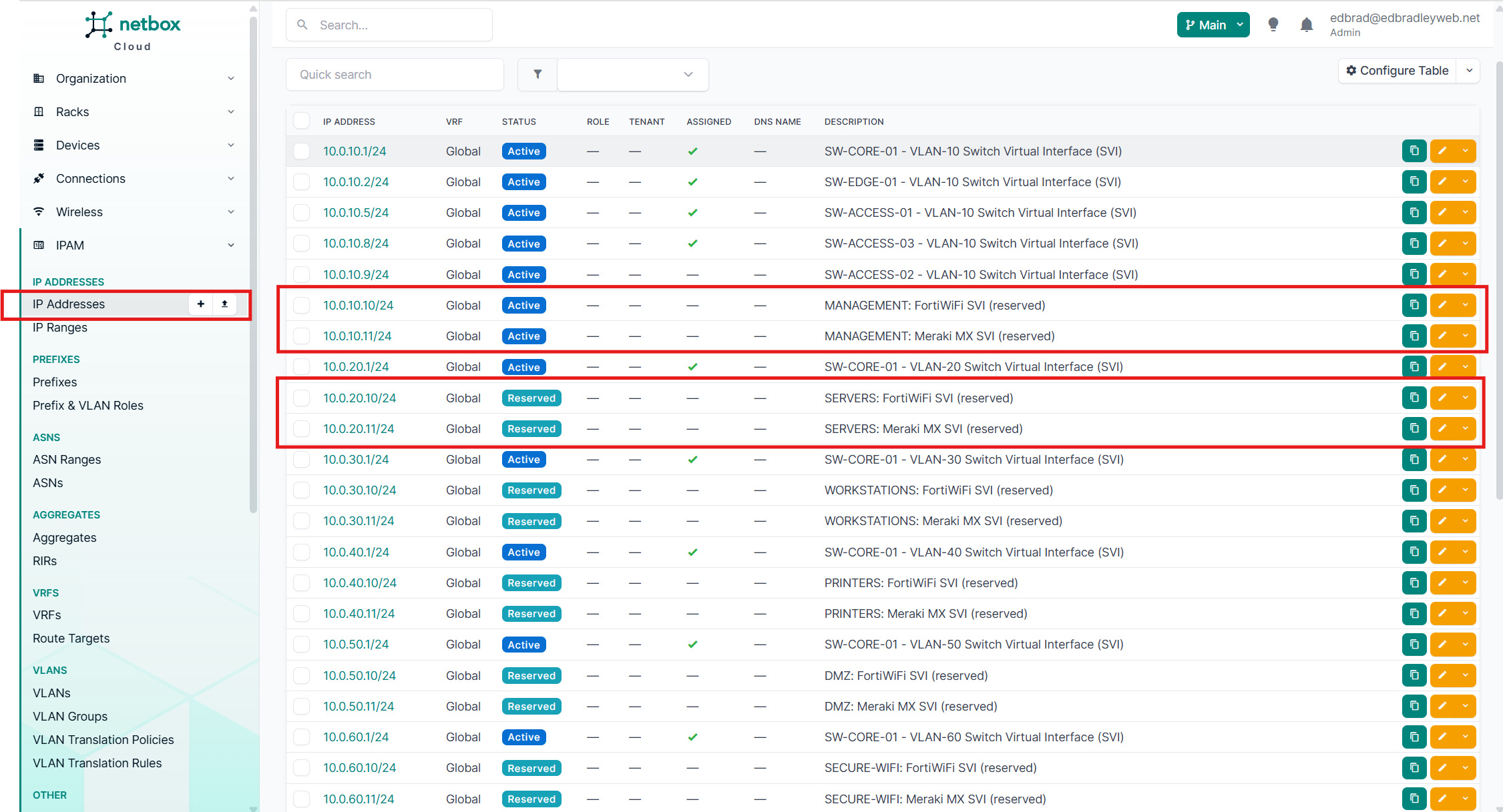
I also imported this table data into NetBox to make sure I have the addressing convention documented in my designated "source of truth":
With the new IP addressing convention in place and documented, I moved on to configuring Policy-Based Routes (PBRs). For this phase of the lab build, I focused on conditional Internet routing for two VLANs:
- VLAN 20 (Servers) – traffic routed through the FortiWiFi 61F
- VLAN 30 (Workstations) – traffic routed through the Meraki MX68W
This setup allows me to experiment with steering different types of workloads through different firewalls. As the lab evolves and additional workloads are introduced, I’ll expand and refine these policies across the other VLANs.
SG350XG PBR Configuration:
On the core switch (SG350XG), I started by creating access lists to match traffic originating from VLAN 20 and VLAN 30. Because the goal of this implementation of policy-based routing is to handle north–south traffic (LAN to Internet), I explicitly excluded any east–west traffic (local inter-VLAN communication) by denying private (RFC1918) destination networks in the ACL. This ensures that only Internet-bound traffic is subject to PBR, while local LAN communication continues to follow "normal" routing paths:
ip access-list extended PBR_SRC_VLAN20
 ! Keep east-west local; only policy-route Internet
 deny   ip 10.0.20.0 0.0.0.255 10.0.0.0 0.255.255.255
 deny   ip 10.0.20.0 0.0.0.255 172.16.0.0 0.15.255.255
 deny   ip 10.0.20.0 0.0.0.255 192.168.0.0 0.0.255.255
 permit ip 10.0.20.0 0.0.0.255 any
exit

ip access-list extended PBR_SRC_VLAN30
 ! Keep east-west local; only policy-route Internet
 deny   ip 10.0.30.0 0.0.0.255 10.0.0.0 0.255.255.255
 deny   ip 10.0.30.0 0.0.0.255 172.16.0.0 0.15.255.255
 deny   ip 10.0.30.0 0.0.0.255 192.168.0.0 0.0.255.255
 permit ip 10.0.30.0 0.0.0.255 any
exit
Next, I defined route maps to specify the “next hop” (the appropriate firewall transit IP) for each VLAN:
! Route-maps (set next-hop per VLAN) ---
route-map PBR_V20_TO_FORTI 10
 match ip address access-list PBR_SRC_VLAN20
 set ip next-hop 10.0.100.10
exit

route-map PBR_V30_TO_MERAKI 10
 match ip address access-list PBR_SRC_VLAN30
 set ip next-hop 10.0.100.11
exit
Finally, I applied the route maps to the corresponding SVIs, so that ingress traffic from each VLAN follows the intended path:
! Apply PBR inbound on the SVIs
interface vlan 20
ip policy route-map PBR_V20_TO_FORTI
exit
interface vlan 30
ip policy route-map PBR_V30_TO_MERAKI
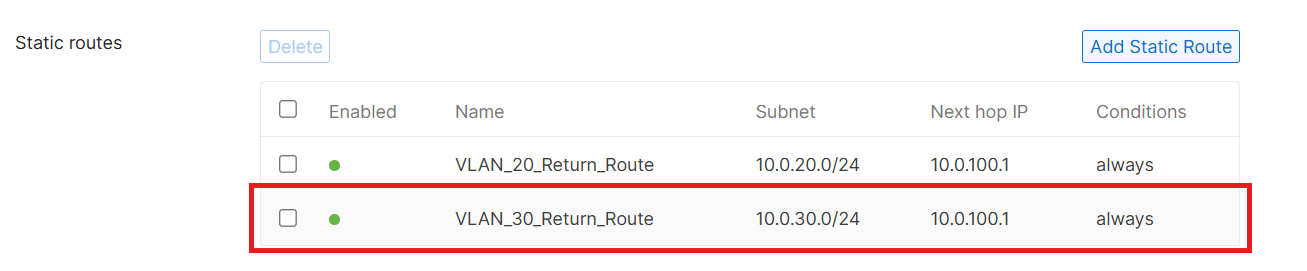
exitTo complete the round-trip, on the Meraki Firewall, I configured a return route, back to the core switch, via the transit VLAN, for the VLAN 30 Internet traffic (along with VLAN 20 - if needed in the future):
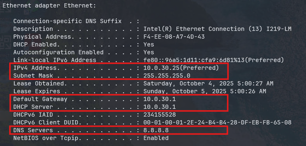
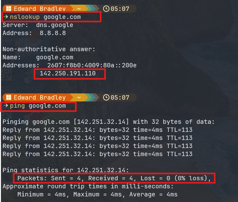
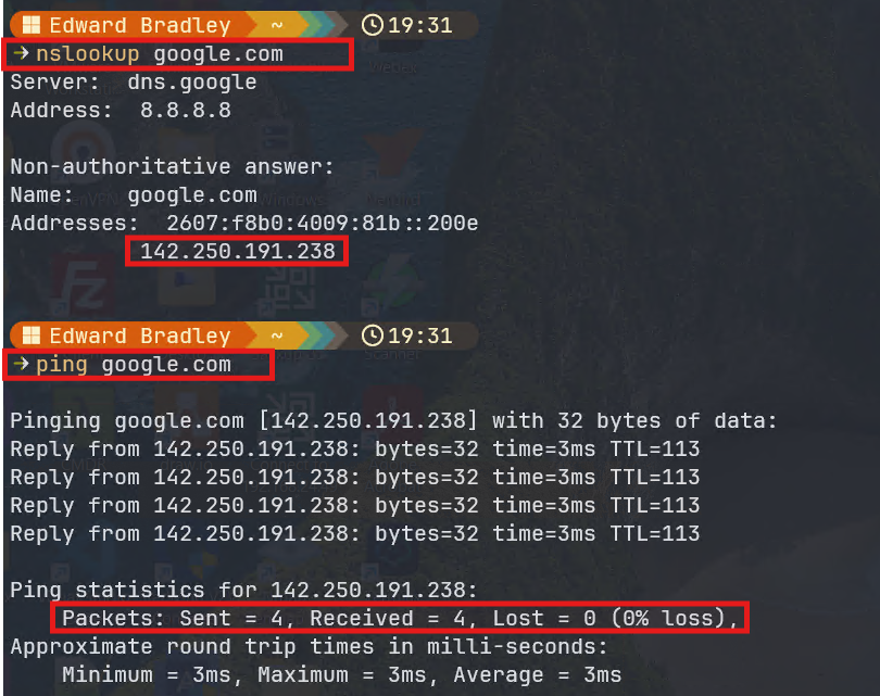
To test, I connected a laptop to an access port assigned to VLAN 30. The workstation was able to successfully ping a public IP address (8.8.8.8), confirming that the traffic was leaving the network through the Meraki firewall. However, DNS resolution initially failed — I couldn't resolve hostnames such as google.com.
The issue turned out to be straightforward: I had forgotten to configure DNS server addresses in the DHCP pool for VLAN 30 (which is being provided by the core switch). After updating the DHCP scope to include public DNS servers, the workstation was able to both resolve Internet hostnames and access websites as expected:
Deploying the Fortinet FortiWifi 61F
The Fortinet FortiWiFi 61F is currently connected to my previous “lab” environment. Its WAN1 interface is configured with an active static public IP address, provided by AT&T. This setup presents an excellent opportunity to simulate a realistic enterprise scenario—one where a single firewall is used to consolidate and route Internet traffic from two distinct network environments. In this case, the goal is to bridge and gradually transition off and retire my old lab network, using the new Home Lab environment exclusively.
Configuring the FortiWifi for the Transit VLAN (100):
The temporary “transition” topology differs slightly from the finalized design: the FortiWiFi remains directly connected to the AT&T CPE router via its WAN1 port. The plan is to eventually decommission the old lab and route the Internet connection through the Edge Switch (FS3900). This approach offers flexibility during the migration phase—maintaining Internet access for both environments while allowing me to test and refine the new network architecture.
Because the FortiWiFi is still reachable from the old lab, I was able to leverage its existing management access to begin integrating it with the new environment.
I started by reconfiguring the Internal2 port to carry Internet-bound traffic for the new lab network.
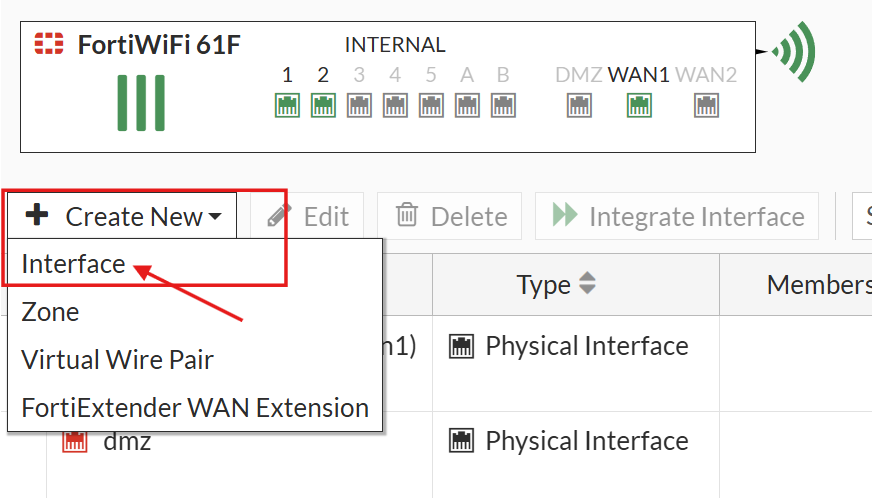
By default, the FortiWiFi’s internal LAN ports are grouped together as a single logical switch. To manage the Internal2 port independently, I first removed it from this logical interface group:
- Navigated to Network → Interfaces.
- Right-clicked on the greyed-out interface labeled internal and selected Edit.
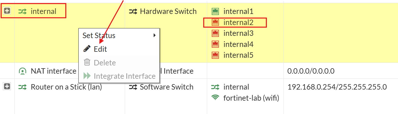
- Removed internal2 as a member of the switch (clicked the
Xto the right of the port name).
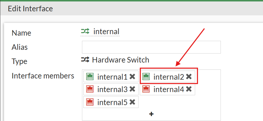
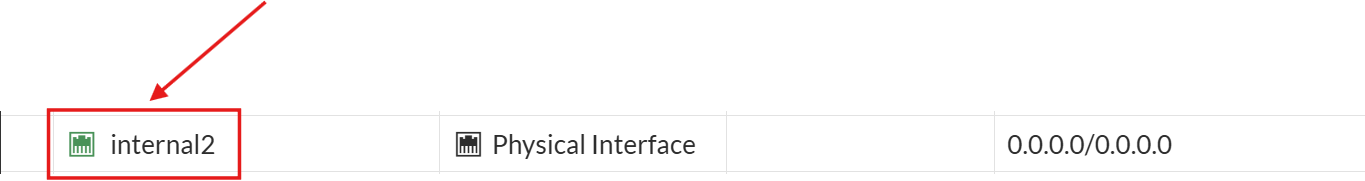
After this change, Internal2 became visible as an independent, configurable interface:
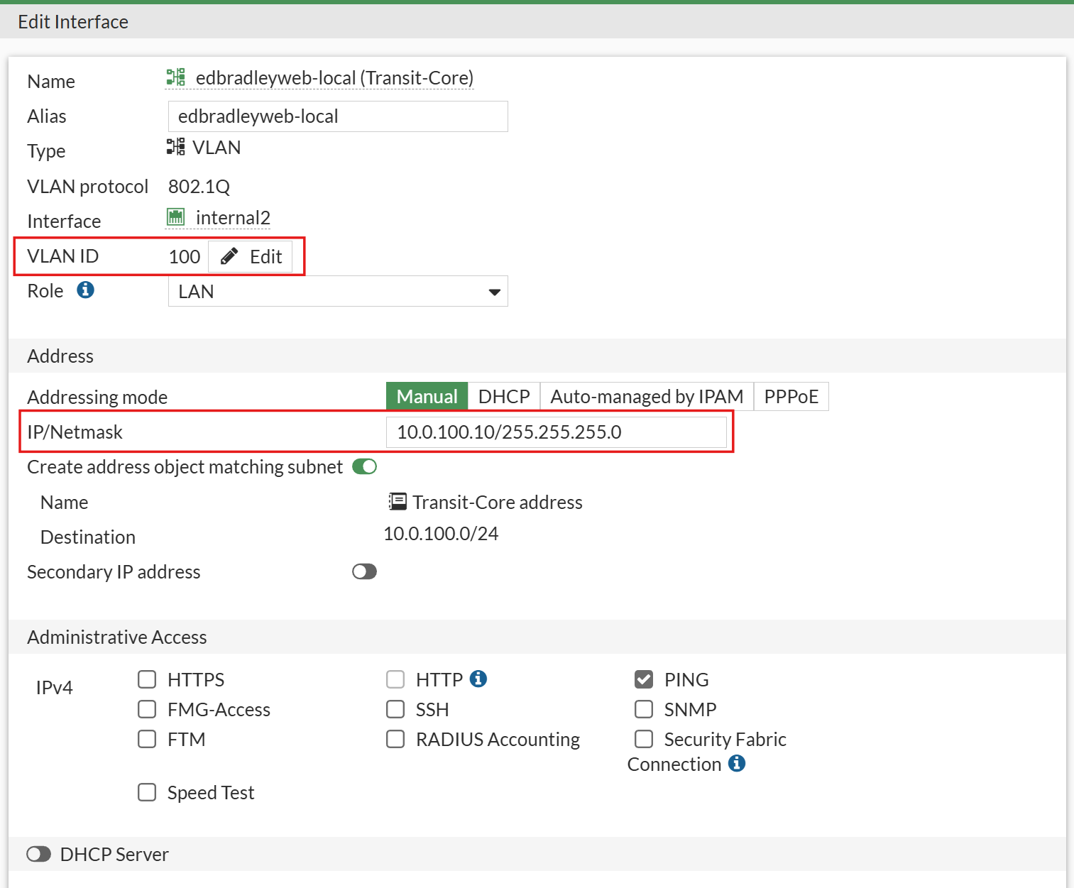
Next, I created a new SVI (VLAN interface) for the Transit VLAN (100), which connects the FortiWiFi to the Cisco SG350XG Core Switch:
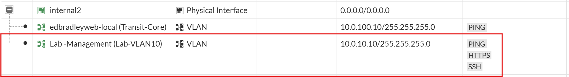
I also extended Management VLAN 10 to the firewall by adding an SVI on the Internal2 port
Configuring the SG350XG core switch for the Transit VLAN (100):
On the SG350XG, I used Port 2 to establish a trunk link to the FortiWiFi. The configuration commands were as follows:
interface te1/0/2
description Trunk_to_FortiWiFi_Internal2
switchport mode trunk
switchport trunk native vlan 99
switchport trunk allowed vlan add 10,99,100
switchport trunk allowed vlan remove 1
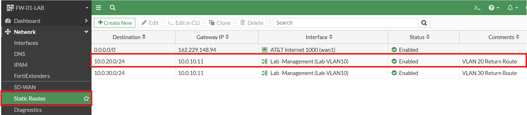
exitTo complete the round-trip, on the FortiWiFi Firewall, I configured return routes, back to the core switch, via the transit VLAN, for the VLAN 20 Internet traffic (and for VLAN 30 - if needed in the future):
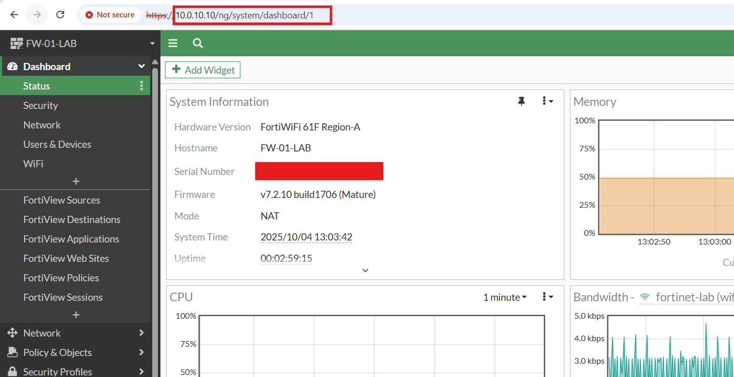
With the Management VLAN (10) SVI in place, I was able to access and configure the FortiWiFi from the new lab network using either the Web GUI or SSH:
Providing Internet Access to the New Lab Network via FortiWiFi:
To enable Internet connectivity, through the FortiWiFi, for the new lab, I created firewall policies on the FortiWiFi, to allow outbound traffic through WAN1 (AT&T):

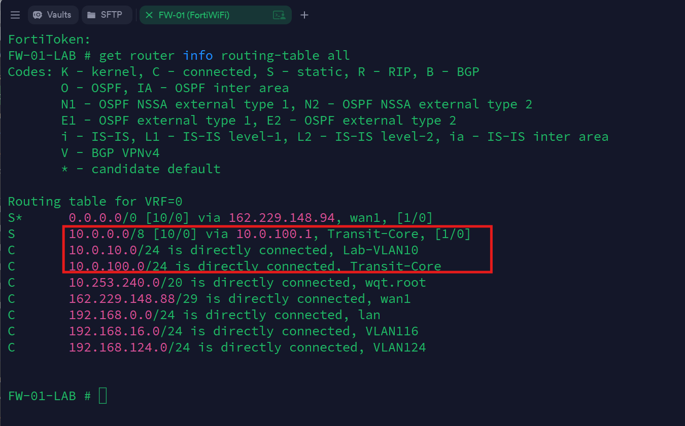
The Policy-Based Routing (PBR) configuration on the Core Switch—which steers VLAN 20 traffic through the FortiWiFi—was already in place, so I confirmed, using the core switch's CLI, that the route was now active:
show ip route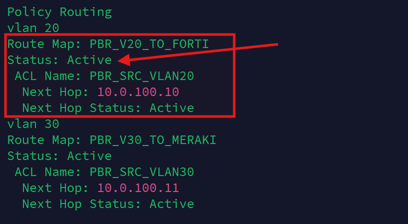
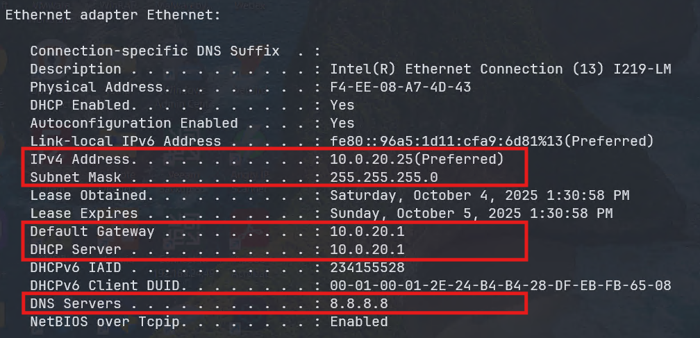
To test the configuration, I connected a laptop to an access port assigned to VLAN 20. It successfully obtained the correct DHCP lease and was able to reach the Internet and resolve DNS via the FortiWiFi connection:
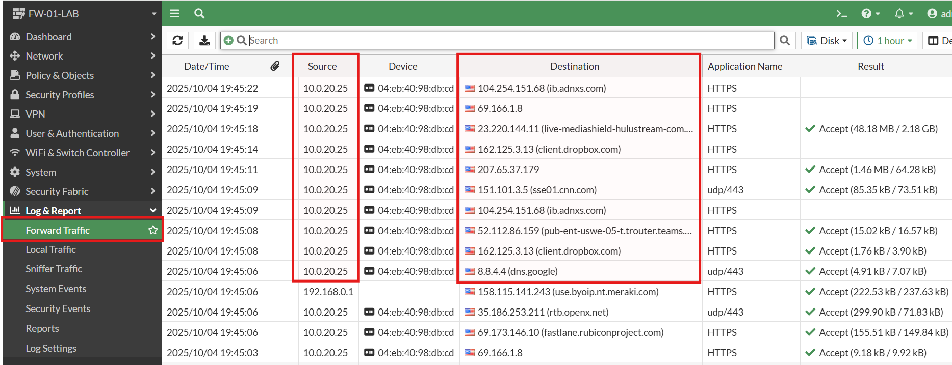
Finally, reviewing the Forward Traffic Logs on the FortiWiFi confirmed that traffic from the test laptop was flowing as expected:
The Firewalls and VLAN 10 (Management) - Inter-VLAN Routing:
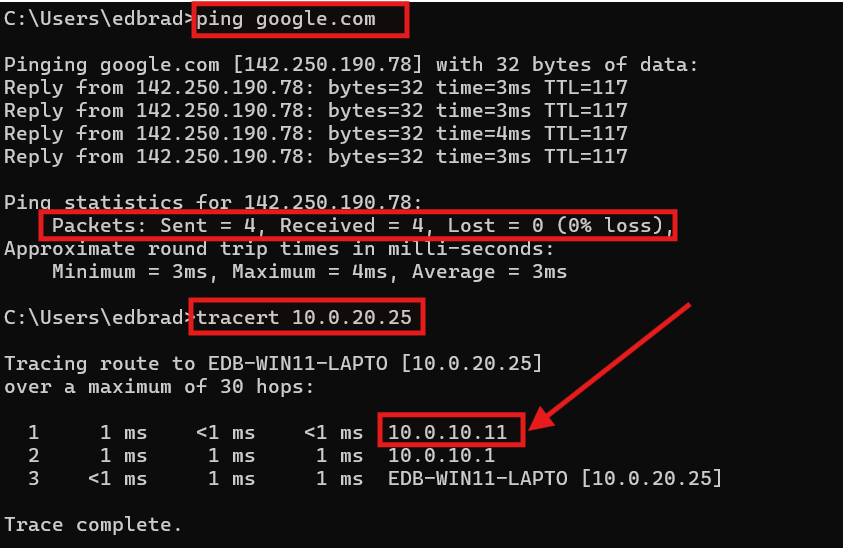
While testing connectivity between VLAN 10 (Management) and the rest of the lab network, I discovered that devices on VLAN 10 could reach both firewalls, but Internet and inter-VLAN communication behaved inconsistently:
- Setting the default Gateway address to the MX68W SVI (
10.0.10.11), allows me to access the Internet AND access the internal VLANs. Internal VLAN traffic is automatically routed through the MX68W:
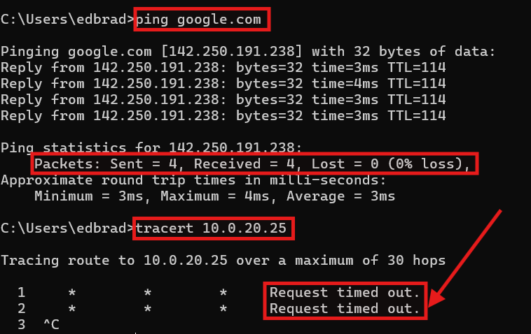
- Setting the default Gateway address to the FortiWiFi SVI (
10.0.10.10), on the other hand, allows me to access the Internet but I am NOT able to access the internal VLANs. There is no available route:
After some research, I discovered that this behavior stems from a fundamental difference between the two firewall platforms. The Meraki MX series automatically handles internal routing and NAT for all VLANs, allowing outbound traffic to flow seamlessly through its WAN interface. In contrast, FortiGate firewalls function as true Layer-3 devices, requiring explicit static routes or policy definitions for each subnet. Without a defined return path, FortiOS intentionally blocks reply traffic to prevent asymmetric routing — a key safeguard in enterprise environments.
⚠️ Why Asymmetric Routing Is Unsafe
🔄 What Asymmetric Routing Means
Asymmetric routing occurs when the path a packet takes to reach its destination is different from the path its reply takes back.
For example:
- A workstation sends outbound traffic through Firewall A.
- The return traffic (from the Internet) comes back through Firewall B.
This creates two one-way, unpaired paths through separate devices.
🧱 Why Firewalls Don’t Like It
Modern firewalls are stateful, meaning they track the state of every connection:
- When a packet leaves the network, the firewall creates a state entry (source IP, destination IP, port, sequence number, etc.).
- When the reply packet returns, the firewall checks if it matches that state entry.
If the return traffic comes back through a different firewall, there’s no matching session in that device’s state table.
Result: the firewall drops the packet — even though it’s technically valid.
This is intentional behavior, not a bug — it prevents:
- Spoofing (fake packets pretending to be responses)
- Session hijacking
- Data leakage (traffic bypassing security inspection)
So, FortiGate (and most enterprise firewalls) block this by design — it’s part of the security model.
🧩 Why It’s Dangerous in Production
Asymmetric routing can cause:
- Intermittent connectivity (some sessions work, others fail)
- Broken VPNs or HTTPS sessions
- Log anomalies (“no session matched,” “invalid state”)
- Inconsistent inspection — some packets bypass the security stack entirely
Even worse, it makes troubleshooting a nightmare, because packets do leave the network — they just never make it back through the expected device.
To temporarily maintain Internet connectivity on VLAN 10, I reverted the DHCP default gateway to the Meraki SVI (10.0.10.11). This ensures packets follow a consistent return path while I refine the FortiWiFi’s routing configuration. The issue arises because both firewalls share the same transit VLAN (100) and participate in overlapping routing domains — a setup that would typically be avoided in production through dedicated transit VLANs or more granular Policy-Based Routes (PBRs).
For now, this workaround keeps connectivity stable while accurately simulating a multi-firewall topology found in complex enterprise networks. The internal “production” VLANs (Servers, Workstations, etc.) do not experience this routing issue since they already use PBRs to steer Internet and east-west inter-VLAN traffic. Once I retire the old lab network and route the FortiWiFi’s ISP connection through the Edge Switch, I’ll introduce a dedicated transit VLAN (perhaps: VLAN-120?) for the FortiWiFi connection to the core, and eliminate this overlap entirely.
Cable and Connection Documentation
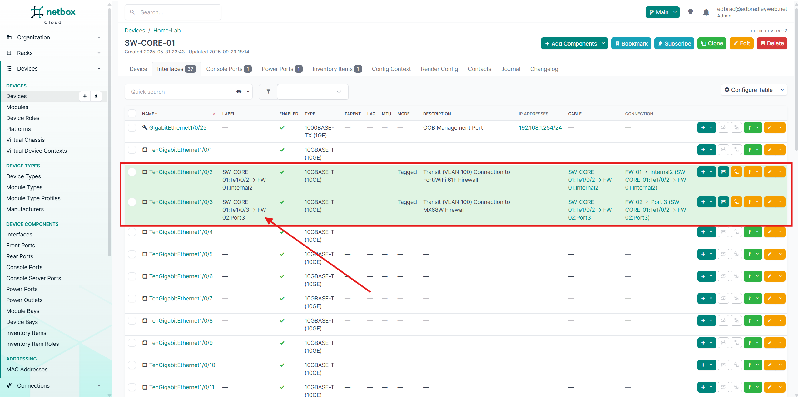
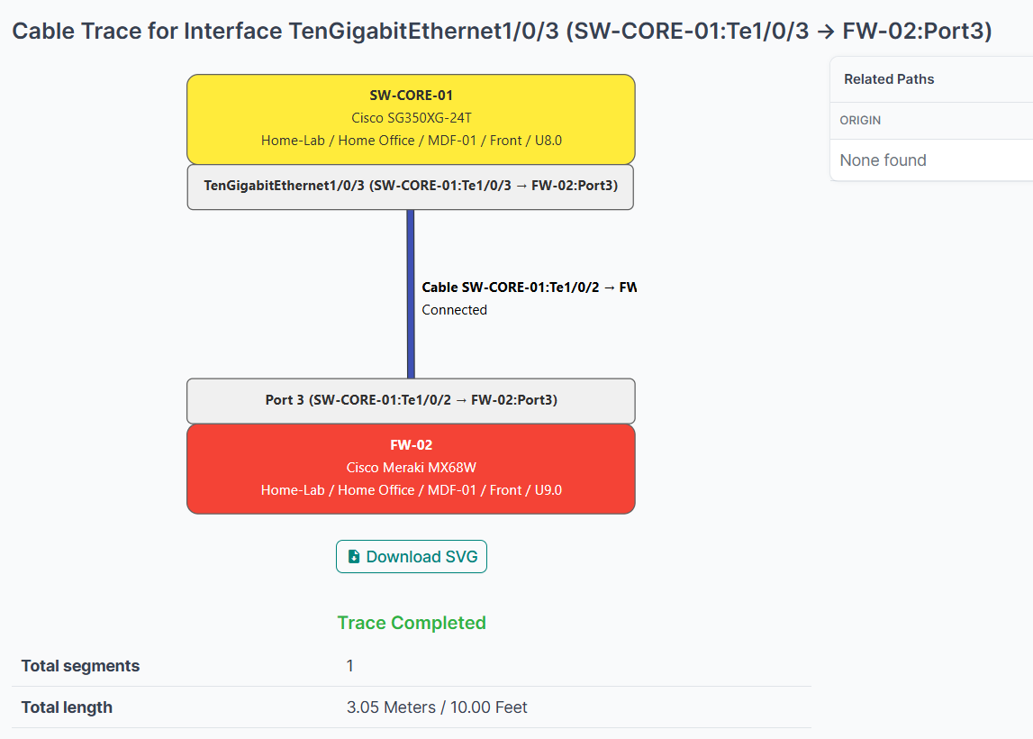
Now that several initial cable connections are in place and communication between devices is confirmed, this is the ideal time to record these details in the NetBox database. As the network grows, NetBox becomes an invaluable tool for tracking and visualizing every physical and logical connection — a major advantage when making changes or troubleshooting connectivity issues.
In addition to documenting endpoints and VLAN associations, NetBox also allows me to define the exact label text that will appear on the physical tags I plan to print and apply to the cables. This ensures consistent, accurate labeling across all network components.
All of the current cable connections have now been entered into the database, as shown below:
🧩 Wrap-Up: Building a Dual-Firewall Network Perimeter
With both the Fortinet FortiWiFi 61F and Meraki MX68W now deployed and integrated into the new lab topology, the network perimeter has taken shape. Each firewall is operating side-by-side, providing unique functionality and management experiences — Fortinet offering granular control and enterprise-level flexibility, while Meraki delivers simplified, cloud-based administration.
Establishing the ISP-to-Firewall and Firewall-to-Core transit VLANs (100–102) — and properly isolating them through the FS3900 Edge Switch and Cisco SG350 Core Switch — enables true dual-firewall operation with clean traffic segmentation. With Policy-Based Routing (PBR) now configured on the core switch, Internet-bound traffic from each VLAN is directed through its designated firewall path. This setup effectively simulates a multi-WAN, enterprise-grade edge network, providing both flexibility and redundancy for real-world testing and learning.
Through this configuration, I can now:
- Test redundant Internet egress and routing policies between ISPs (AT&T and future Comcast).
- Experiment with firewall-specific security policies (Fortinet vs. Meraki).
- Observe north-south vs. east-west traffic flows across VLANs.
🔑 Key Takeaways
- FortiWiFi and Meraki coexistence demonstrates real-world multi-firewall design, complete with routing conflicts, NAT behavior differences, and interoperability lessons.
- Transit VLAN design isolates and controls ISP traffic, simplifying monitoring and troubleshooting.
- Policy-Based Routing (PBR) allows flexible Internet steering by VLAN, enabling me to simulate load balancing and failover scenarios.
- Documentation in NetBox ensures all cable mappings, VLANs, and interconnects remain clearly defined for visibility, maintenance, troubleshooting, and planning.
🧱 To-Do / Next Steps
- Migrate the FortiWiFi WAN connection from direct AT&T CPE access (ATT-CPE-01) to being delivered through the Edge Switch (VLAN 101), aligning the setup with the finalized lab topology.
- Introduce a dedicated transit VLAN (for example, VLAN 120) between the FortiWiFi and Core Switch. This will fully segregate the firewalls and eliminate the potential for unsafe asymmetric routing, ensuring predictable, secure traffic flow.
- Create dedicated management ACLs to restrict administrative access to trusted endpoints only, reducing the attack surface for management interfaces.
- Plan and implement inter-VLAN ACLs to enforce least-privilege communication between network segments while maintaining essential cross-VLAN functionality.
- Configure Syslog and SNMP forwarding to LibreNMS and the Security Stack (Wazuh / ElastiFlow / Suricata) to provide unified visibility, alerting, and traffic analytics.
- Begin preparing for Active Directory and RADIUS integration, which will introduce centralized authentication and authorization for both wired and wireless clients, which I will begin building in my next Post.
In the next post, I’ll begin to focus on Identity & Access — Building Centralized Authentication. This phase will center on deploying the first Active Directory Domain Controller to establish a unified identity management framework within the lab (and expanded in the cloud later on). The domain controller will provide centralized authentication, DNS, and policy enforcement across all network segments, creating the backbone for secure and consistent access control.
The HPE DL20 server hosting Active Directory is equipped with iLO remote management, enabling secure, out-of-band access (via VLAN 10) for monitoring and maintenance — even when the operating system or production VLAN (20) is unavailable. Together, these capabilities bring enterprise-grade reliability and control to the lab, closely mirroring the resilience and structure of a professional datacenter environment.